Changing Your Modeling Approach for Better Designs (Part 2)
This is the second in a series of three blog posts that coordinate with an eBook that was provided on the Solid Edge site. If you missed the previous project, you can check it out here. You can download the eBook here.
If you don’t already have Solid Edge, and you’d like to try this project, you can download a free 30-day trial of Solid Edge.
This series seeks to inform you of how easy it is to learn synchronous technology and to help you create some models that will introduce the ease of creating parts and the simplicity of making changes to your existing models.
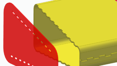
In this second example, a spoiler is created for multiple car trunks. The spoiler is shaped like π. This math-fun spoiler is created quickly with closed regions of geometry and uses peer level parts to finalize the spoiler posts to match the trunk and spoiler faces.
Model 2: Car Spoiler
In this example, we’re going to work on a rear spoiler for a car. We’re going to ignore aerodynamics and use a spoiler that looks like π. We’ll add in a different car trunk. Using synchronous technology, we will alter the original model with ease to make it fit several styles of automobile.
To begin, create a metric part file. Start sketching a path for the outline of the spoiler top. The sketch dimensions are shown below.

To create the geometry that will be swept along this curve, we’ll create a rectangle sketch on a plane perpendicular to the path. For this model, the overall size is 700mm wide and 100mm tall.

These two sketches will be used when we choose to create a Swept Protrusion.

Finally, round the edges of the piece with a 25mm radius. To perform this in a single step, choose the All Rounds option in the command ribbon. This file can be saved as Spoiler Top and closed.

Next, let’s create the posts that the spoiler will sit on to connect to the trunk. To create the model, we will do it in the context of the assembly. Begin by creating a new metric assembly file. Bring in the Trunk 1 file that you received with this eBook and let it ground at the 0,0,0 location.
Save the File as Spoiler Assembly 1.

Next, drag and drop the Spoiler Top part we created previously into the new assembly. Position it with a planar alignment from the Top plane on the spoiler piece to the Top plane on the trunk so that it is 400mm above the trunk. Next, add a planar alignment to position the part 1250mm from the Right plane of the assembly.

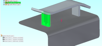
Now we can create the two supports that will connect the spoiler to the trunk. The easiest way to create these pieces is to use the faces of the existing pieces in the assembly. First, create a new metric part named Spoiler Mount 1 within the assembly.

Within the new part, create a sketch that is 100mm wide and 400mm deep.

Choose the region created by the sketch and extend it. To extend to a specific surface, in this case, the trunk, set the extent option in the command ribbon to From-To.


To create the face that extends to the underside of the spoiler, let’s Close and Return back to the assembly. Now we’ll use the Replace Face command to shape the top face of our mount.

Because synchronous technology allows us to make changes at the assembly level, we can begin the Replace Face command by selecting the top face of the mount.

Next, choose the underside of the spoiler to extend the mount face too.

Now the face of the mount matches the bottom face of the spoiler.

Editing into the part will show you that the assembly driven change has been carried down to the part level. This shows how synchronous technology gives you peace of mind when creating files of making edits.

Save and close the file. We’re not going to fully constrain the part at this step in the process. We’ll come back to it after we add mounting holes in a later step.
Now, let’s create another mount on the opposite side of the spoiler. We’ll use Create in Place with a new metric part file to begin the process. Save the file as Spoiler Mount 2.

Begin by creating another sketch 100mm x 400mm. The region that creates should be extended down to the top face of the trunk.

Close and return to the assembly.

The current location of the second mounting post needs to be adjusted. We’ll use the Steering Wheel to get the part in the correct position. For this trunk, we’ll move the part to 1000mm from the center of the trunk.

Now that the mount is in the correct position, we’ll use Replace Face again to correct the top face to mount directly against the underside of the spoiler.

Now both mounts are correctly placed and have correct mounting faces.

The next step is to create the mounting holes for the two posts that hold up the spoiler. To do this, we’ll use holes in the trunk to create matching holes in the spoiler.
First, edit into Spoiler Mount 1. From inside the mount, create a hole. Position it based on the location of the holes that are already in the trunk. To perform this, we need to be sure that Peer is toggled on in the tools tab in the Edge Locate group.
Using the hole command, create two tapped holes with a Finite Extent.

To place the holes, align them to the two coordinating holes in the trunk by using Project to Sketch to bring both mounting hole outlines to the current model.

Now place the holes at the center points of the geometry.

Save and close Spoiler Mount 1. Now inside the assembly, Edit the part Spoiler Mount 2. Create the same Project to Sketch circles as we did in the previous step.

Now that the mounting holes are in the posts, the mounts can be positioned in the assembly.

To position Spoiler Mount 1, create a Planar Mate between the top/rounded face of the mount and the bottom of the spoiler.
Next, create Axial Alignment relationships between the center of the tapped holes in the mount and the clearance holes in the trunk.

Now the first spoiler assembly is complete.

The next step in this project is to create a second trunk assembly by using a new trunk and altering a copy of the spoiler using synchronous technology. To begin, we’ll create a copy of the assembly using Design Manager.
Open the assembly and set the files to Save As. After assigning their new filenames, choose Perform Actions.

Now that the new files are shown in Design Manager, we can replace Trunk 1 with a new file, Trunk 2. Again, click to Perform Actions.

Now we can open Spoiler Assembly 2 in Solid Edge. Note that the component files are changed to the new files. Also pay attention to the PathFinder. We can see that some of our parts are no longer fully constrained. As we adjust the parts to achieve the changed design, we’ll re-constrain the items.

With the spoiler position being incorrect and the mounting holes now in the wrong area, let’s alter the position of the pieces by using the steering wheel. Begin by selecting the three parts and moving them to align the posts with the holes that are in this trunk. Note that the faces are incorrectly rounded and angled for this trunk.

Now that the spoiler is in the position we need, let’s alter the overall size of the spoiler. For this trunk model, we’ll make the spoiler longer in each direction from the center of the trunk/assembly. Window-select the left side of the spoiler. This will be easier if you toggle off the display of the trunk. Next extend the spoiler to make it 50mm longer.

Now repeat the movement on the right side of the spoiler. Keep in mind that in order to allow this change to happen in one step, toggle the select option to Face Priority.


The next step is to alter the mounts. We can do this by using Replace Face again to match the unique angle of this trunk.

Begin with selecting the lower face to match it to the top face of the trunk.

The bottom face of the first post is now perfectly matched to the angle and radius of the trunk.

Now use the same command to alter the post on the opposite side of the spoiler.

This example walked you through some of the ease of edits that synchronous technology can offer. With edits happening at the assembly level, there is increased peace of mind that the changes were carried to all necessary pieces. Watch the full video of this project here.
About Polished Edge Consulting, LLC
Polished Edge is a Solid Edge Administrator/Consulting business that Melissa Schultz formed in the fall of 2018. The primary purpose of the business is to help people use Solid Edge. With nearly two decades of experience in Solid Edge, Melissa is offering CAD Administrator services to all Solid Edge customers. Whether your business is too small to pay a full-time admin, or your full‐time admin is too busy with daily support to write training, Polished Edge Consulting has a solution for you. With Polished Edge Consulting, all Solid Edge using companies have access to tailored training, custom problem resolution, proven best practices and synchronous technology.