Changing Your Modeling Approach for Better Designs (Part 1)
This is the first in a series of three blog posts that coordinate with an eBook that was provided on the Solid Edge site. You can download the eBook here.
If you don’t already have Solid Edge, and you’d like to try this project, you can download a free 30-day trial of Solid Edge.
This series seeks to inform you of how easy it is to learn synchronous technology and to help you create some models that will introduce the ease of creating parts and the simplicity of making changes to your existing models. In this first example, we create a shaving razor using synchronous technology. We walk you through creating an initial model that can be altered and changed to allow for several versions of a set of models.
Model 1: Double Edge Safety Razor
In this example, we’ll model a razor using synchronous technology, with the help of a video demonstration, as well as step-by-step instructions. This model will feature several handle options.
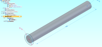
To begin, let’s create the handle. Begin with a new metric part file saved as Handle 1. To create the model, the initial piece of the handle can be created using the synchronous technology Cylinder command. This allows a single step process instead of creating a sketch and then creating an extrusion that uses that sketch. The smaller part of the handle will have a diameter of 10mm and will be 100mm long.

Now draw a circle at the end of the cylinder that has a diameter of 15mm.

The closed geometry will create a region. Select the region and extend the body 75mm.

The next step is to draw a sketch to use in a Revolved Cutout. The sketch should be drawn on the outer edge of the handle and on the Right plane.

Choose Revolve in the feature group. First, choose the areas that will remove the material.

Then select the axis of the cylinder as the axis of revolution. Enter 360°.

Now that the grip of the handle is complete, we can alter the connection end.

Create a sketch on the center plane of the handle to remove material from both sides of the sketched region. Selecting the region will show the direction.

Toggle the symmetric extents button in the command ribbon. Now choosing a direction arrow on the steering wheel will create a cut that removes material evenly from both sides of the sketch.

The removed material will allow us to create the connection end of the handle.

Now use the blend tool to add a 1mm radius blend to all edges.

Next, we will create a cutout to seat the eject button. When pushed, this button will detach the razor head (disposable) from the handle. This button will be a separate part in our assembly. Begin by creating a sketch that is 4mm wide and centered on the shaft. The geometry’s distance from the end of the shaft should be 2mm. The rest of the length is not important, so we won’t waste time locking it down.

Now choose the region and extend it down 1mm into the piece.

This completes the first part in our assembly. This file can be saved and closed.

Now create a new metric assembly file and name it Razor. Drag and drop the Handle 1 file into the assembly from the Parts Library tab.

Next, use the Create in Place command to place a new metric part file in the assembly. Name it “Connector.”

Begin by placing a cylinder on the base coordinate system. Match the 10mm diameter of the handle with a 20mm length.

Now we will create a flat in the same location as on the handle. Making sure the Peers button is toggled on in the Tools, Edge Locate group, use Project to sketch to add the line that will be 2mm from the center point of the cylinder.

Add a circle on the same plane that is larger than or equal to the 10mm shaft. Choose the created region and use the steering wheel arrow to remove material from the cylinder.

Because we’re designing this part within the assembly, we know that we’re cutting the correct part of the cylinder. Now add a 1mm blend to the three edges of the cylinder as shown below.

Next, we’ll add a U-shaped piece that will attach the razor blades. Lock the sketch plane to the front face of the cylinder by using the F3 button. To orient the design window to the plane, use the quick key Ctrl+H.

Now sketch the geometry shown below.

Select the created region and extend it to the opposite end of the shaft.

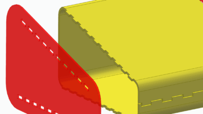
Now use the steering wheel to adjust the angle of the face. Start by selecting the top face of the connector.

Now, to get the next level Steering Wheel, click the blue dot. Then position it over the midpoint of the start of the cylinder.

Select the torus and rotate it -5°.

Next, we’ll put bosses on the edge of the tips of the U shape. The 1mm round should be 2mm long. Then create that cylinder on the opposite arm as well.

Finally, create a cut at the end of the handle. We’ll use the matching face on the handle to ensure this cut is the same as the handle cut. Using Project to Sketch will allow us to easily mirror the geometry to the connector.

Select the created region and extend it down to match the depth of the coordinating cut.

Close and Return back to the assembly. Looking at the Connector, it appears too long. Let’s shrink the length of the connector easily with synchronous technology.

This change can be made at the assembly level without needing to go back into the part file. In the Select tool, be sure to choose Face Priority. Then window-select the end of the shape.

Choose the arrow that points toward the handle and move it 10mm in that direction.

That looks better. Because we made the change with synchronous technology, we didn’t have to edit into the part to make the change.

The next part of the assembly is going to be brought in as a subassembly. Go to the downloads that you got with this eBook and drag in the Blade assembly. The first relationship should be a planar mate between the faces shown below.

Next, create an axial alignment between the peg on the connector and the corresponding hole in the blade assembly.

The third relationship can be an angle between the top face of the blade and the angled face of the connector. Set the angle to 30°.

The last step in the design process for this razor is to create the eject button. This button won’t function in our assembly since we’re creating this assembly with limited complexity for the eBook. Regardless, we can create an initial draft of the button.
With the assembly open, choose Create Part in Place.

Place the Coordinate System at the start of the cutout in the handle. Name the file Button.

Select the Extrusion command and click the cutout in the Handle and Connector files.

Accept the selection and extend the faces to 2mm.

Next, create a blend on the handle end of the razor that is 2mm.

Close and Return back to the Razor assembly. Inside that assembly, we can create relationships to position the Button in place. The first relationship should be a Mate to put the bottom of the button onto the Handle.

Next can be a Mate to put the side face of the button to the coordinating face on the connector.

The final relationship to position the button should be another Mate.

That finishes the initial configuration of the razor assembly.

Now, let’s create a draft of this assembly. In the Application Button, New menu, choose the Drawing of Active Model button. That shortcut allows us to choose the template without needing to search for the assembly that we already have open.

When the Drawing View Creation Wizard comes up, click the Drawing View Layout button in the command ribbon. Choose the right view as the Primary View and toggle the top, right, and iso view on. With this set, all four drawing views will be placed at one time.

Save the draft as Razor.

Next, we’ll create additional handle options for this razor. Open Handle 1 and save it as Handle 2. Inside this new version of the handle, we’ll start by making a smaller shaft. Begin by selecting Cutout 2 and deleting it.

Left with the original shaft of 10mm, add a blend of 2mm to the far end of the shaft.

Now, sketch a profile that will be a cutout from the shaft.

Choose the region and cut it through the length of the shaft.

Select the resulting cutout and create a circular pattern feature.

Set the occurrences to 12.

This completes the new handle. Save and close the file.
We can now save a new copy of the razor assembly and update the associated draft. Open the original Razor draft and assembly and choose Save As. Use the name Razor V2 for the new file.

Inside the assembly, replace Handle 2 with Handle 1.

Inside the draft, use the Application Button to access the Info, Edit Links option. In this dialog, the target assembly can be altered to Razor V2. After changing the target file, the draft views will be enclosed in a thin black border showing that they need to be updated.

Use the Update Views button.

See the full video of this project here.
About Polished Edge Consulting, LLC
Polished Edge is a Solid Edge Administrator/Consulting business that Melissa Schultz formed in the fall of 2018. The primary purpose of the business is to help people use Solid Edge. With nearly two decades of experience in Solid Edge, Melissa is offering CAD Administrator services to all Solid Edge customers. Whether your business is too small to pay a full-time admin, or your full‐time admin is too busy with daily support to write training, Polished Edge Consulting has a solution for you. With Polished Edge Consulting, all Solid Edge using companies have access to tailored training, custom problem resolution, proven best practices and synchronous technology.


Comments
Leave a Reply
You must be logged in to post a comment.
Hi,
One question: which the function of button part?