Changing Your Modeling Approach for Better Designs (Part 3)
This is the third and final in a series of blog posts that coordinate with an eBook that was provided on the Solid Edge site. In case you missed the previous projects, here’s where you can find Project 1 and Project 2.
You can download the eBook here.
If you don’t already have Solid Edge, and you’d like to try this project, you can download a 30-day free trial of Solid Edge.
This series seeks to inform you of how easy it is to learn synchronous technology and to help you create some models that will introduce the ease of making parts and the simplicity of making changes to your existing models. In this third example, a model of a TV wall mount will be created using sheet metal files.
Model 3: TV/Monitor Wall Mount
In this example, we’ll create a wall mount for a flat screen television.
Synchronous technology can offer a huge benefit in the sheet metal design environment. In this environment, the intuitive design process that synchronous technology offers shows itself in the cleanest ways possible. Let’s start with a model that is in the sheet metal environment.
With a new inch sheet metal template, create a file named Wall Plate. If we were making this model in Ordered, we’d likely begin with creating a contoured flange that was the overall edge profile of the part we need.
To begin, double-click the Material line in the PathFinder to open the Material Table dialog. In the Gage Properties tab, set the material to Steel and the Sheet metal gage to 10 gage.

In this example, to showcase the ease of synchronous technology creation in the sheet metal environment, let’s begin with a tab that is the size of the flat face of our wall plate. Sketch a rectangle that is 33-½ inches wide and 9-¼ inches tall.

This geometry will create a region. By clicking the region (any space closed by geometry) a tab will be created.

Choose the direction for the tab to create in and click to place it.

Now we can add the first bend to this part. Simply select the top, long face of the plate and choose the direction to extend it. In the screenshot below, we’ll choose the smaller of the two directional arrows.

Next, enter a value of 39/64. Solid Edge will convert this fraction to a decimal.

Now, click the resulting edge to create another flange. This flange will also be 39/64 of an inch.

The new top edge of the plate will look like this.

The bottom face of the plate is next to get additions. The two flanges will be the same length as those on the top edge of the plate and will also be turned out and then up.

The next step on the wall plate is to create cutouts to remove material from the center of the plate. The cutouts will be 5 inches wide by 4 inches tall. Creating the geometry on the face of the plate will mean it is a region that we can select, and it will remove the material if we choose the direction arrow that goes through the plate.

Note that the dimensions on the plate are not locked. They drove the size of the cutout and its position. The cutout can be copied easily using the Control button and the steering wheel.

The two matching cuts can be mirrored about the Right (YZ) plane of the plate.

Now the plate is ready for the slots that will be used to bolt the plate to a wall.

The first slot can be positioned at the end of the plate. It’ll be used to pattern the slot across the entirety of the plate on the top and bottom. Choose the slot command and click to place the slot at the top left corner of the mounting face. The line to define the slot should have a length of 1 inch.

After that line is positioned, the Slot command will become active. Select that command and enter the settings to make the slot .375 inches wide and give it Arc ends.

After that slot is placed to go through the plate, choose the Rectangular Pattern command. Set the slot properties to place an X count of 20 instances and a Y count of 2. The rectangle they are placed on should be 31-1/2 inches wide and 7 inches tall.

Now that the slots are placed, our final step is to add the flanges to the ends of the plate. To select the length of the flange, choose the endpoint of the existing flange. That’ll create a flange that will be 39/64 inch long.

Place a flange like this on both ends of the plate.

The wall plate is now complete. The next step in the creation of this mount is to create the brackets that connect the television to the wall plate. The shape of the brackets is unique to hang on the plate flanges. This item will also be made from sheet metal using synchronous technology. To begin the model, create a new inch sheet metal file and save it as Bracket.

Begin the model by setting the Gage properties to 10 gage steel. To open the Material Table, double click on Material in the PathFinder. In the Gage Properties tab, choose 10 gage from the drop-down menu.

Next, create a rectangular sketch. Place it on the XZ plane at 18-1/2 inches tall and 1-3/8 inches wide.

Choose the Tab command and select the rectangle. Point the tab in the direction where the material should be applied. On an example like this, the direction of the material is less important than with others, but we’ll direct it in the positive direction.

Now, we can add flanges to both long sides of the tab. Click the edge and choose the arrow that points in the correct direction.

Duplicate the process on the other edge of the tab.

This bracket will bolt directly to the rear face of the television. To start, we’ll add holes to the top half of the mounting face. Place the first 3/8-inch hole centered in the middle of the tab and down ½ of an inch from the top face.

There should be 15 holes in total for a pattern height of 8 inches.

Create 1-inch long lines on the face. Each of the five lines will be spaced ½ inch away from each other with the first starting 11 inches from the top of the bracket.

Next, we’ll add the slots to the bottom half of the bracket. The slots will be 3/8-inch-wide to match the mounting holes. With the lines on the face of the bracket, the Slot command will now be available. Inside the Slot Options dialog, set the preferences to show a slot width of 0.375 inches and Arc ends.

Click OK and begin selecting the lines to create the slots.

Here’s what the bracket will look like now that the holes and slots are on the mounting face.

Next, we need to add the cutouts that will allow the bracket to hang off the wall plate. The geometry needs to match the mounting flanges. Start a new sketch on the side face of the Bracket. The profile of the sketch is shown below. This cut can be copied to be placed three times on the top of the bracket.

The pattern on the bottom half of the bracket will share some similar geometry as the top part of the pattern. Use the top part of the cutouts above and mirror it so the pattern looks like the one shown below.

When drawn on the side of the bracket, the enclosed geometry will create regions. Those regions can be highlighted and will remove the material from both sides of the U when you choose the direction arrow and depth. Notice that on these cuts we’re using dimensions and relationships to constrain the size. That’s because they need to remain as drawn to accept the wall plate hooks.

After the cutouts, create a chamfer on both ends of the bracket. All four edges should be chamfered. Choose the Break Corner feature and set the Chamfer button in the Command Ribbon.

After selecting the corners, enter ½ inch as the setback.

Create a new inch assembly file. Save it as TV Mount.

Inside the file, drag and drop the Wall Plate into the assembly. This part will automatically be grounded to the 0,0,0 point because it is the first part in the assembly.

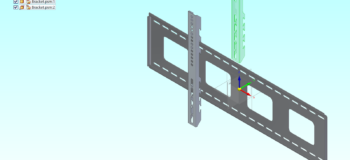
Next, drag and drop a Bracket into the assembly. This part will need to be positioned. The first relationship should be a planar mate between the faces shown below.


The second relationship should be a tangent between the cylinder on the middle hook and the top edge of the wall plate.

After that relationship, the bracket should be in the second hook.

The third relationship will be to adjust the position of the bracket in the X direction. The first bracket should be positioned 7-7/8 inch away from the center plane of the wall plate. Use a planar align to position the part using the center plane of the bracket and the center plane of the plate.

Now that the first bracket is positioned, we can bring the second bracket in. Although Solid Edge offers us several ways to bring part and sheet metal files into assembly files, the most effortless in this situation would be to select the bracket and use Ctrl + C to copy and then Ctrl + V to paste another into the assembly file. Note that the location your cursor is in within the design window is where the pasted part will be positioned.
Use the same three relationships to constrain the second bracket.

Now that both brackets are on the plate, we can bring a television into our assembly. The file can be downloaded from the site you downloaded this eBook to. Drag and drop the television into the assembly from the Parts Library.

The first relationship should be a planar mate that connects the back face of the television with the mating face of the bracket.

Next, align a mounting hole on the television with the middle mounting hole on one of the brackets.

Finally, use a planar align relationship to align the top face of the television to the top face of the wall plate. During the creation of the relationship, use the float option to allow the alignment to be parallel without being at a zero-distance position.

This completes the television mount.

See the full video of this project here.
About Polished Edge Consulting, LLC
Polished Edge is a Solid Edge Administrator/Consulting business that Melissa Schultz formed in the fall of 2018. The primary purpose of the business is to help people use Solid Edge. With nearly two decades of experience in Solid Edge, Melissa is offering CAD Administrator services to all Solid Edge customers. Whether your business is too small to pay a full-time admin, or your full‐time admin is too busy with daily support to write training, Polished Edge Consulting has a solution for you. With Polished Edge Consulting, all Solid Edge using companies have access to tailored training, custom problem resolution, proven best practices and synchronous technology.


