Challenges and solutions for process plant design
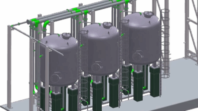
Engineers have to deal with many different tasks for process plant design from the overall layout of a complete plant, to design and integration of specific equipment. Modern plant design methodologies can take advantage of the latest CAD software to speed the design process, and ensure a smooth transfer of engineering data (with no disjointed export/import steps) from one process step to the next. These modern CAD tools can help close the gap between plant, equipment and mechanical engineering while speeding the design process, ensuring quality and keeping costs at manageable levels.
This blog post was written working with our software partner CAD Partner and references their Smap3D plant design software.
The journey begins: How engineering software tools are transforming the plant design process
Process technology had its beginnings in piping and boiler engineering, but it has now developed into an interdisciplinary science. In order to design the plant required to perform a complete process, this can no longer be divided into basic operations with only one physical process, such as mixing or evaporation. Instead, these basic operations are strung together to comprise the overall process. This approach is used to create a high level diagram of the process.
 P&ID diagram created using Smap3D
The next step is to create the detailed process and intstrumention (P&ID) flow chart. In the P&ID flow chart, all components required to operate the facility such as containers, vessels, pumps, compressors, heat exchangers, piping systems, valves and gauges are symbolically displayed and connected with lines that represent the complete system.
In process plants the individual processing stages flow into each other in a continual, connected procedure. In order to complete the process, pipelines are needed to convey materials from one stage to the next. It is vitally important, in the detail engineering stage , to plan and process these stages quickly and accurately in order to achieve successful process plant design.
Certain areas require more specific attention during the design process. For example the whole area of hydraulic and pneumatic control systems for the supply of lubricants, fuels, and cooling and heating cycles. Other examples extend from small pumps and pumping stations to heavy duty cranes. To implement a 3D plant design system for these tasks can be a costlyand complex proposition as off-theshelf 3D CAD software often lacks the functionality and automation needed for the process plant design engineer to complete his work efficiently.
Key areas of focus for optimizing plant design
These are some of the main focus areas for optimizing the process plant design process:
- specific design tools for the initial concept design phase
- automation for generating piping designs and routing
- automatic checking for design errors (eg. Interference checking)
- minimize errors by automatic generation of BOMs and parts lists
- eliminate manual data entry into related systems
- intellectual propert for your design process should be protected
- easy and fast to make design changes when needed
- automatic creation of 3D isometric diagrams
The performance advantage for top performers
Independent research firm Tech-Clarity have analyzed performance of engineering-to-order manufacturers and concluded that the top performers have better processes in many different aspects of quoting, engineering, and manufacturing custom products. And the end result is that top performers report that they perform “very well” 3.5 times as frequently as their peers in the area of engineering leadtimes and 2.2 time as frequently in having accurate manufacturing documentation. You can read the full research paper “Driving engineering-to-order differentiation and profitability” here.

What to look for in process plant design software

1. Ability to define pipe classes to be used for a specific project
With pipe specifications, the compatibility of components (fittings, valves, etc.) is uniquely defined in line with particular company or project specifications for pipe system characteristics (diameter, material, etc.). The central definition of pipe classes prevents user errors, saves time and ensures a more consistent end product.
2. A specific P&ID solution
A specific P&ID solution is needed, not just an adaptation of a 2D drafting system. The P&ID solution should use the same pipe classes as in the 3D solution and be simple to integrate into 3D. It should include symbol libraries and symbols from common standards and contain intelligent connections between symbols and lines, so that they can be easily and conveniently moved. It should allow you to generate parts lists and analyses that can be exported, processed in formats such as XML or MS Excel. An integrated design review and validation capability is also important.
3. A 3D piping design solution
The piping software solution should be able to read and utilize all the information from the P&ID diagram.
It should use the library of pipe classes that the designer specifies should be used for a specific project and should be integrated into the 3D CAD software so that equipment locations and pipe routing can be accurately planned. Changes in the pathway and/or diameter of the piping should be accomplished quickly.

4. Isometrics
An isometrics module should be available that generates isometric images directly from the 3D plant assembly model in the 3D CAD software. It should recognize various parts lists such as materials, cutting and welding lists and reproduce them on the drawing and in a separate text file. It should also offer a fast transfer of the pipeline data to external programs.
This is not the end of the journey…
You can investigate Smap3D plant design software to meet the needs described above. You can also read a case study on how one manufacturer is using Smap3D software together with Solid Edge to design and manufacture brewery equipment.