CAMWorks for Solid Edge: Solid Edge for Manufacturing, Old Insulator Stack – by Dave Ault [video]
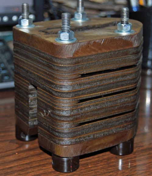
Here is an obsolete Westinghouse part that still is in service with electric utilities that needs to be replaced. As is typical with many of these obsolete parts there is no blueprint or file provided so I have to have a physical sample to measure from. This one had a lot of small variances as you can imagine both from manufacturing tolerances which were generous and spark erosion on the inside from use. I use a Gold Faroarm to reverse engineer things like this. In general you can tell what the intent was with the old parts and keeping in mind that simple numbers like fractions were used in many cases on old parts you can interpolate from your collected data and arrive at an accurate and useful part.

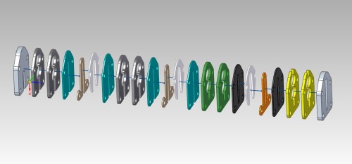
In this case there were ten different parts in the stack and I will be able to use one jig to cut nine of them.

Once you have the parts created what is the problem to be solved for machining these is how to hold them for cutting. In past versions of SE it has been a multi-step rigamarole thing to get this done. In ST6 much to my delight this is no longer true. Now it is a simple thing to create an assembly and drag a part into place on a block and create a perfect workholding device for cutting. What I will be showing is the setup for one type of part and how to hold it in place while machining. Being able to do this for a family of parts quickly and easily is key to how much money you are going to make on short run items. I will have twelve sets of these to cut and more than likely will not have any again for a year. Please note that I will not be machining the jig block itself for the sake of time here. It is what happens elsewhere that is interesting. So follow me as I demonstrate how the combination of ST6 and CAMWorks makes more money with less hassle in my shop.
Later this month by the way CW4SE will have assemblies capabilities in it if you care to use it. With this method that I am going to demonstrate however you pull your xyz zero off of the corner of the block for the cut plan and when you clamp your part in you are good to go. Subsequent parts in this family of parts can be brought into the assembly and positioned with their common hole center patterns and each of them can be saved out as separate parts just like the first one was and cut plans derived for them using the common xyz zero. It is not necessary to have a separate assembly file you have to bring in for every single variation here. In reality it is not necessary to have an assembly file at all in your CAM plans to still be able to benefit from assemblies. Obviously the holes in the rectangular blank stock are the first step in a separate operation with a different clamp method working off of stock xyz zero. Two vice-grips and a strip of metal on another 6″ x 6″ plate will do for blasting the holes out.
Folks, bear with me on the occasional hiccup here. It is time out of a workday to do this and you would not believe how many times you have to go through these things before they are perfect. Try making a video yourself and see. I spent enough time on this one to get close and that is good enough. And yes I know after reviewing the video that I moved the block .09 and not .10 for the zero point but you understand the intent here and can duplicate the correct result on your own parts with the directions here.
Join me as I create the jig and part and then cut with SE ST6 and CW4SE


