Bluesurf and the NURBS Mesh
Today I’m going to use the mesh from the part you can download from the previous post. That has a series of 6 sketches in it from which we can make Bluesurfs in various curve arrangements.
For this you set the selection in the Cross Section Step to Single, click, right click, until you have all the curves selected for that direction. Then switch to Guide Curve Step, and do the same. As you add curves, watch the shape of the surface get closer and closer to the curves. This also helps you see the interpolation that we’ve talked about in previous articles.

The NURBS mesh here is easy to see, because we’ve kind of recreated it with all of the sketched curves. But when I trim out an area in the middle, let’s take a look at how that works. You can use the surfacing visualization tools to help you have a look at the mesh, and the curvature.
If you’re going to do real work with this tool, and not just make screen capture blobs, you have to know what all the controls do. The image below shows two controls. The one connected to the middle of the curve is the Tangency Control. The options are Natural, Normal to Selection, and Parallel to Selection. Normal/Parallel are relative to the sketch plane, or the face that an edge is attached to. If your curve selection involves edges, you will get some additional options I’ll mention further down.

Note: If the selected curve is a Keypoint Curve (3D curve), then the only available option is Natural. It would be nice here if they allowed some sort of directional control such as a plane, a line, or a coordinate system vector. If you want to establish a tangency direction when lofting from a Keypoint Curve, you will have to make a reference surface.
The larger control to the right in the image above is the tangency weighting. The short orange line with the green dot is normally red when not selected. You can use this to control the tangency weight or stiffness for the entire curve or just the indicated node. If you click on the number, you’ll get the scroll box shown in the image, and you can use the mouse wheel to change the number. If you have the surface fully constrained with curves in both directions, the tangency weighting may not do much aside from causing the feature to fail. So, I would only use this if you have curves in only one direction.
Also notice that the weighting number has two icons next to it. These control whether the number you are editing controls just the node where the handle is connected or if it controls the weighting for all the nodes in the whole curve. This is important to pay attention to. Default value for this is 1. Less than 1 means the surface will remain tangent to the original direction for less than the default distance.
Just a word to the wise, working with complex features is tricky enough. Fiddling with all the numbers makes it even trickier, and tougher to troubleshoot should the feature fail. I recommend the simplest set of options that gives you the shape you want. Don’t fiddle with stuff unless you need to.
Next I’m trimming out a little patch. To do this, I’ve just sketched a rectangle on a plane that will project onto the surface.The Trim feature is used for this. Select Target wants you to pick a surface body that is to be trimmed. Select Tool wants whatever you’re going to cut with, typically a sketch, a curve on the surface or another surface body. In the Region Select step, remember to select the portion of the surface that you want to discard.

Notice that below, the patch we have trimmed out of the mesh isn’t lined up with the mesh. Let’s see if the Bluesurf still works in this situation. I’m going to patch the hole that we just trimmed out using the Bluesurf controlled by edges, not reusing the original curves (although we could do that to try to get a good match between the new surface and the previous surface).
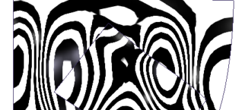
Selecting open edges of a trimmed surface instead of sketches or curves is important because it helps you work directly from existing geometry. It also allows you to establish boundary conditions (tangent, curvature continuous, and so on) directly to the surrounding surface geometry rather than going indirectly through sketches or planes. We can use Zebra Stripes to ensure that the patch is smooth across the edges.

The Zebra Stripes setting is on the Inspect tab, next to the Surface Visualization button. Zebra Stripes is simply a visualization technique to judge the smoothness of a surface accomplished by making the part reflective and surrounding it with imaginary walls with painted stripes on them. This is like looking at the reflection of your surroundings in the reflective panel of a car when you are looking for dents in the parking lot.
You can see that the new patch does not fit very smoothly with the rest of the surface. This is because we haven’t set the tangency/continuity options for the 4 edges. I’ll leave that for next time, as this is getting a little long…


Comments