Automation – Parametric Parts
This post introduces the most common and sought after use of automation in Solid Edge – creating and controlling Parametric Parts via an external program.
Using the Solid Edge API it is easy as 1-2-3
Grab a Variable, Edit it and Bob is your uncle !
The previous introductory article used a Console Application which lacks a descent GUI for user interaction. This post on Parametric Parts introduces Windows Forms which are commonly called dialogs.
Start Visual Studio Express and on the Start Page or from the File menu, select New Project…
Select Visual Basic from the left side panel and Windows Forms Application from the middle panel. The area on the right side shows a small description of what is chosen.

Name the project as ParametricPart or ParametricShaft since parameters of a simple shaft will be modified through the program. Specify a location for the project.
Click OK in the New Project dialog and leave it there. Switch to Solid Edge and create a Shaft by extruding a circle and also create the keyway. Rename the dimensions by double-clicking each, so the end result looks like shown in image below:

Save the part and switch back to Visual Studio where an empty dialog called Form1 is waiting to be painted. That’s Right – the Form is no different from a canvas of a Paint program like MS Paint where you draw different shapes on the dialog which is your canvas.
The shapes called Controls are all available from the Toolbox, which if not visible, can be accessed from the the menu View > Toolbox.
Also make sure you have the Properties window visible from View > Properties Window. This can be used to change various properties of the canvas a.k.a Form and the controls placed on
it.

Now that you only have the Form, change its properties as below:
• Text – Parametric Part – The text in the title bar of the dialog.
• TopMost – Set this to True – so your dialog always float on top of Solid Edge and does not get obscured by any other application.
• Startup Position – CenterScreen – Not absolutely essential but good to have this setting.
• Maximize and Minimize Box – False – again not compulsory, but just for practice.
• Opacity – just for Fun
Click the Start Debugging ![]() icon or press F5 to preview the dialog. Switch between any open application including Solid Edge and note how the dialog always stays on top of other applications without getting obscured or hidden.
icon or press F5 to preview the dialog. Switch between any open application including Solid Edge and note how the dialog always stays on top of other applications without getting obscured or hidden.
Close the dialog by clicking the x in the top-right corner of the dialog.
From the Toolbox double-click the textbox icon ![]() This will place a textbox or Edit box in the center of the dialog. Move around the textbox by dragging and also size it using its handles.
This will place a textbox or Edit box in the center of the dialog. Move around the textbox by dragging and also size it using its handles.
With the textbox still selected, change its Name property to txtShaftDiameter where,
• txt is a convention to prefix names for controls. A checkbox would similarly have a chk prefix
• ShaftDiameter denotes this textbox will allow user of the program to enter a value for the diameter of the shaft. Also note that S is big and D also is written big. This style is called the camel hump notation and makes the code more readable.

Similarly add more textboxes to hold other parameters of the shaft and the keyway. Drag around to place controls on the Form and using the alignment indicators which appear in magenta and blue promptly as seen in image besides, arrange them neatly one below other.
Change the Name property of the textboxes to txtShaftLength, txtKeywayDepth, txtKeywayWidth and txtKeywayLength to hold the corresponding values for the shaft.
Similarly add Labels  and change their Text as shown in the image and align them besides the corresponding textboxes.
Add a button  and set its name property to btnUpdate. Also Change the Text property to Update Part as shown.
Press F5 again to preview your dialog again. Close the dialog and select Project > Add Reference…
As explained in the previous article, add references to Solid Edge.
Double-Click on the Form in an empty space but not directly on a control. A new Tab opens the code window for the Form. The cursor is placed between two lines of code already added:

Again as explained in the previous article, press Ctrl+Home to move to the top of the code window and add the following lines:
Imports System.Runtime.InteropServicesImports SolidEdgeFramework
Imports SolidEdgeConstants
Move the cursor inside the Public Class Form1 and declare Visual Basic variables for Solid Edge and the Solid Edge Variables as below:

• The oApp variable for Solid Edge is same as explained in the previous article.
• The new variable oVars stores all the variables from the Variable Table of Solid Edge.
oVars will help us access the Solid Edge variables and change their values.
The moment we do this, Solid Edge automatically changes the model to reflect the new values.
Move the cursor further below to between Sub Form1_Load and its corresponding End Sub:
Private Sub Form1_Load(sender As System.Object, e As System.EventArgs) Handles MyBase.LoadEnd Sub
The Form_Load Sub i.e. SubRoutine is automatically executed when the form starts. This functions similar to the Sub Main in the a Console application discussed an earlier article.
Type the following lines:
oApp = Marshal.GetActiveObject(“SolidEdge.Application”)

oVars = oApp.ActiveDocument.Variables
This stores all variables from the Current i.e. Active i.e. Currently Active document into oVars.

Note the two separate tabs for the code and the Form i.e. the dialog. Click the Form1.vb [Design] tab or just press Ctrl+Tab to view the Form again
Double-click the button for Update Part to enter its code stub in the code window and type:
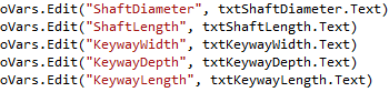
oVars.Edit(“ShaftDiameter”, txtShaftDiameter.Text)
This tells Solid Edge to Edit the variable by name ShaftDiameter and change its value to that entered into the txtShaftDiameter Textbox on the Form.

Edit the value of other variables as below:

Further, it is necessary to recompute the model:
oApp.ActiveDocument.Recompute()
Finally, if the model dimensions are changed such that it needs to be Zoom Fit, this can be done using code as below:
oApp.StartCommand(SolidEdgeConstants.PartCommandConstants.PartViewFit)
This underlines the importance of using the Imports SolidEdgeConstants statement at the top of the code window for its by virtue of this Imports statement that we can use the constants defined in the Solid Edge API to start commonly used commands. This is an important technique to note and learn.
Press F5 to test the program. Enter values for the various parameters in the textboxes and click the Update Part button.
Solid Edge should update the shaft model using the new values. The beauty of this approach is you can keep the dialog floating, edit one or several values at a time and just press the Update button. The model will update with each click of the button and Zoom Fit too.
In the next article in the automation series, you will learn how to pull current values of the variable from Solid Edge into the textboxes so users of your program can tweak the current value without checking it first in the Variable Table. Also you will learn how to Save As the modified model to a new Solid Edge Part.
More detailed information on the various methods to edit or modify variables in Solid Edge is explained here by Julian Guillo.
In case you decide to try out something different or further to what is discussed here and run into any problems or errors, do not hesitate to post a query on the Solid Edge Developer forum.
Simply click the New Message button found at the top of the page.
~Tushar Suradkar


Comments