Automated process plant design with Smap3D and Solid Edge


Design of a complete processing plant together with the associated piping and equipment is a complex task that requires specialist techniques and knowledge. Off-the-shelf 2D and 3D CAD software can be used to support the design process but huge benefits can be achieved by using specialist plant design software that is integrated closely with your CAD software. Smap3D Plant Design software from CAD Partner integrates closely with Solid Edge to provide an excellent solution for process plant design. According to Christian Montag, group leader of mechanical design at brewery equipment manufacturer Kaspar Schulz “with the integrated solution for pipeline planning, we are working up to three times faster than the previous process. The combination of Solid Edge and Smap3D, piping design, PDM and ERP has improved our efficiency, reduced costs and increased quality.“
Integrated process chain for plant design
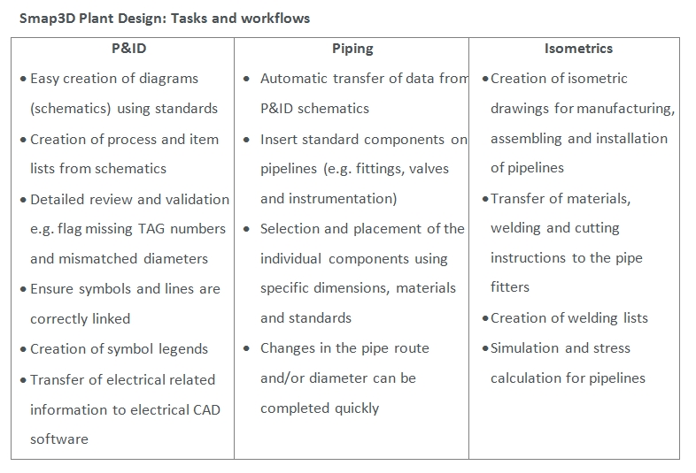
Smap3D Plant Design provides three components in a single software solution for an integrated process design chain: Smap3D P&ID, Smap3D Piping and Smap3D Isometrics. Depending on the individual requirements these specialized programs can be used individually or together with Smap3D transferring data between the individual programs. A separate export or import of data is not needed. At the same time, Smap3D Plant Design enables a centralized, as well as company and project-specific, definition of pipe classes. This is an essential baseline that ensures standard, or customer specific, piping and associated components are used in the design process. This in turn assures the quality and reliability of the final plant design while keeping design and manufacturing costs down. With predefined pipe classes, the conformity of associated components such as valves and other fittings to these standard sizes is assured.

Some key Smap3D product features
- A key baseline is a centralized database of standard pipe classes, and the database can be configured for specific customers and projects
- A to-do list that provides a direct link from 2D P&ID diagrams to 3D piping design in Solid Edge
- Includes Smap3D standard part libraries and Smap3D PartFinder that support efficient use of Smap3D Piping software
- Substantially increases design process consistency
- Smap3D Isometric to create isometric drawings, with output in DXF, DFT, SLDDRW, DGN and PCF formats for collaboration with suppliers and customers
Smap3D P&ID: Intelligent P&ID diagram creation
The 2D flow diagram (also known as the P&ID schematic) is the first step and a key document in the process chain for plant design. SMAP3D supports the relevant international standards for P&ID diagrams; for example in the USA P&ID diagrams and all associated content for process engineering plants are regulated by ANSI/ISA 5.1 to 5.5. and similar standards exist for Europe. All systems and components like containers, pumps and fittings are represented as symbols, and pipelines are represented by connecting lines marked with nominal width, pipe specifications, ID number (TAG) and more.

Using Smap3D P&ID the user has all the relevant charts, diagrams, drafts, and design evaluations at hand in a single software package. Smap3D P&ID also automates and simplifies frequently repeated tasks. All drawing sheets, project sheets and reports are template-based and are fully configurable to meet the needs of specific customers.
Smap3D Piping: Piping system design
Smap3D Piping works as a fully integrated ‘add-in’ within Solid Edge. The program automates the design and modification of 3D pipe systems within the Solid Edge assembly environment, a complex task that an engineer or pipeline planner would otherwise have to carry out in separate stages. The basis of this highly automated 3D pipeline design is the use of pipe specifications tables in which the associated components (fittings, flanges etc) are determined by the relevant company, department or project-specific pipe system characteristics.

A large number of automatic design routines for the fittings required for pipeline design are also available. These include the automatic placement of bends, tees, collars, flanges and gaskets and more. Further intelligent automations are the creation of pipeline reductions or expansions, the splitting of pipes when a maximum length is reached and the placement of connectors. These routines speed the design process and ensure a consistent and high-quality end product.
Smap3D Isometric: Instructions for pipeline manufacturing
Isometric graphics creation is the third step of the typical process chain for plant design. A pipeline isometric is a technical drawing in the form of an isometric 3D image that is used to aid the design and manufacture of pipelines. The pipeline isometric is not to scale but contains the information that piping manufacturers and installation engineers need to complete their tasks accurately and efficiently.

This blog post was written in conjunction with our software partner CAD Partner and is the final post in a series of three. You can also read the case study for brewing equipment manufacturer Kaspar Shulz, and an overview of the challenges for process plant design. You can also register for a free trial of Smap3D Plant Design software and watch a video of Smap3D and Solid Edge in action.


Comments