Assembly PathFinder Part1: Settings and Symbols
 You can’t get the most out of Solid Edge without knowing the assembly PathFinder pretty thoroughly. A lot of the tools will be obvious, things like mousing over items and they highlight in the graphics window. In fact, Art Patrick, the planner for assemblies functionality in Solid Edge tells me that the developers work to make the functionality in the PathFinder as similar to the functionality in the graphics window as possible, so if you RMB on a part in either place, you get (mostly) the same set of options. This helps the interface be more internally consistent.
Settings
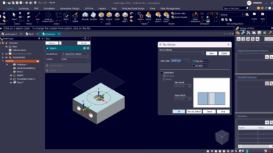
Let’s start with some settings. In general, it is recommended that you use the opaque PathFinder just to tax your video card less. I know, my screen shot to the right uses the transparent setting. But for best performance and reliability, make it opaque with a plain color at AppMenu>Solid Edge Options>Helpers>General, and turn OFF Show

PathFinder in the Document Window.
From the Help
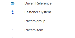
Another great piece of information comes from the Solid Edge Help. I found this after a search for “assembly pathfinder”. There is a legend for 35 of the most commonly seen symbols in the assembly PathFinder. This might be a good one to print out and tape to the side of your monitor for reference until you learn most of the symbols.
Undockable PathFinder Panel
One of the cool things I like about the PathFinder is that you can dock the window where ever you like inside of the Solid Edge window, or you can pull it outside the window and put it on a different monitor. This can help a lot when you have a very busy PathFinder. I use two monitors, one is landscape as usual, but the second is portrait for reading (and writing) long blog articles and lists of emails. Very long PathFinders with a lot of parts in an assembly work great in this configuration. It also saves some precious graphics window real estate as well.
The Lower PathFinder
I understand there are a few different names for this, but I’m going with The Lower PathFinder. These are the items at the bottom where assembly relations show up. Select a part in the assembly, and its mates show up in the Lower Pathfinder. There are some symbols and colors used here that aren’t listed in the Help Legend.

Notice the purple text for one of the mates. That’s a mate between grounded parts. Solid Edge identifies this kind of thing because the mate isn’t really doing anything. It may be costing you assembly calc time because the system has to figure that sort of thing out, and identify it, and then if there are a lot of them, it will definitely cost you. So as a best practice, this kind of thing should be suppressed if you might need it again, or ideally just removed.
Also the little gray arrow next to the purple mate just calls attention to the fact that there’s some sort of an issue. You may see this arrow in other places in the PathFinder.

To the right we have a number of issues. The red mate symbol with the red cube edges symbol means there are missing references – probably a face that was mated to has been deleted.
The red circle with the line
through it is a suppressed mate, and we just talked about the purple text.

The part symbol with the lightning bolt means the part has a conflicting relation, and the gray arrow is pointing out the red relation later on. Notice the pair of relations shown to the right. These two are conflicting, and the one with the arrow is unsatisfied. The mate without the arrow is satisfied, but conflicting. This kind of thing makes troubleshooting easy, Even the tool tips in this situation tell you what to do to resolve the situation (delete or suppress the first unsatisfied mate of the conflicting pair).
…Continued in Part 2…
There is so much information and functionality in the assembly PathFinder that I’m going to have to chop this article into two parts. Come back next time when you’ll hear about reordering, groups, and RMB functionality.

Comments