An example of literal “Reverse Engineering” using Solid Edge
An example of literal “Reverse Engineering” using Solid Edge
Steve Sheldon, December 2018
At the start of the American Civil War there was a great shortage of weapons, for both the North and South. To meet the demand, federal arsenals were emptied, where it was discovered that a large number of obsolete flintlock muskets were still kept in store. Given the dire shortage of weapons, it was decided to convert these arms with their obsolete flintlock ignition systems to the modern percussion cap technology of the day. This conversion work was done by federal government arsenals and private contractors on their behalf.
One of the contractors that took on this work was the firm of Hewes and Phillips, located in New Jersey. In addition to fulfilling state contracts for New Jersey, H&P also did a batch of conversions for the federal government. These conversions were performed on unrifled (smoothbore), Model 1816, 1835, and 1840 flintlock muskets.

Model 1840 flintlock musket. Credit: Wikipedia
Because smoothbore muskets were only accurate to a distance of about 100 yards, they were equipped with front sights only, much like modern shotguns, as the expense of the rear sight was not considered necessary at such short ranges. When H&P undertook the federal conversion contract, in addition to converting the arms from flintlock to percussion, they also added rear sights with the expectation that they would also be rifling the muskets’ smooth bores. However, the arms were needed so urgently that they were sent out into the field unrifled, making these conversions unusual in that they were smoothbore muskets with both front and rear sights.
Fast-forward to today. Today there are competition shooting organizations, such as the North-South Skirmish Association, that compete using original and reproduction firearms from the era. For those who compete in smoothbore competitions, original H&P muskets are highly sought after because with precision target loads, these firearms are quite accurate enough to benefit from having a rear sight. Sadly, there are no modern reproductions of historical smoothbore muskets with rear sights. So, if you want to shoot a smoothbore musket with the advantage of both a front and a rear sight, it’s an original or nothing.
However, there is a reproduction of the Model 1842 smoothbore musket produced today by Chiappa-Armisport. The Model 1840 was the last flintlock musket produced by United States arsenals. It was immediately superseded by the Model 1842 percussion smoothbore musket. Except for the lock and breech end of the barrel, the Model 1840 is nearly identical to the Model 1842. This makes an enticing possibility to “retro-vert” a Model 1842 into an H&P conversion of a Model 1840 musket.

Reproduction Model 1842 percussion musket. Credit: Chiappa Firearms
To effect the historical conversion from flintlock to percussion, two major changes had to be made to the original arm. First, the lock mechanism had to be changed. This was effected by removing the priming pan from the outside of the lock, along with the frizzen and its associated spring mechanism. Then, the old flint-holding hammer was replaced with a percussion hammer. H&P utilized Model 1842 hammers for this conversion, which means I was able to re-use the hammer from the reproduction Model 1842 being converted! In fact, all of the reproduction Model 1842 lock internal components will fit directly into a Model 1840 lock plate. So, I was able to re-use all of the Model 1842 lock components! As luck would have it, reproduction castings of Model 1840 lock plates are available from The Rifle Shoppe, so making a reproduction H&P lock assembly was quite easy.
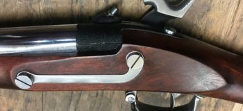
 Close-up of the lock and breech of an H&P Model 1840 conversion. Note rear sight. Credit: James C. Altemus.


Raw Model 1840 lockplate castings from The Rifle Shoppe.


The polished reproduction Model 1840 lock plate fitted with reproduction Model 1842 lock components.
Secondly, the breech end of the barrel had to be modified to accept a cone, or nipple, upon which a percussion cap was placed. This cone was threaded into a tapped hole in a bulge, or “bolster” on the side of the barrel. Hewes and Phillips used what is known as a patent breech conversion. This is a procedure where the back few inches of the original flintlock barrel were cut off and threaded, and a new breech section was screwed in place. The new breech had an integral bolster for the cone.

H&P Patent Breech conversion. Note the new breech that threads into the original barrel. Credit: James C. Altemus.
On original Model 1842 muskets (and most muskets of the era, for that matter), the breech/bolster end of the barrel was forged in one piece with the barrel itself. The open end of the breech end of the barrel was closed by the use of a threaded plug, which included the tang. But as luck would have it, it is expensive to manufacture modern barrels in that manner, so most modern manufacturers of percussion muskets also use a “patent breech” means to manufacture them, with a cast breech end being threaded to the barrel! This means that we can unscrew the reproduction Model 1842 breech from the reproduction barrel, and design and manufacture a new one to thread into place!

Chiappa-Armisport reproduction Model 1842 barrel and breech components showing modern manufacturing technique with separate breech and barrel pieces, which mimics the historical flintlock-to-percussion “Patent Breech” conversion method.
The big engineering effort to this project is creating a new breech. So the first order of business was to get the reproduction Model 1842 breech off of the barrel and scan it to get a mesh model that we could bring into Solid Edge to reverse engineer.


Removing the reproduction Model 1842 breech.
With the breech removed, I used modeling clay to re-shape the bolster to approximate the shape of those seen on H&P Federal conversions:


Using modeling clay to mock up the reproduction Model 1840 breech to look like an H&P Patent Breech.
I then used a 3D scanner to import this geometry into Solid Edge as a mesh body.


Original breech mocked up with clay and 3D scanned into Solid Edge.
As you can see from the above images, the 3D scanner is astonishingly precise, even picking up the stampings in the part. It also picks up slight imperfections in my clay additions. I didn’t want these imprecise features to cause problems during CNC machining, so my task was to convert this to “real” CAD geometry using Solid Edge Reverse Engineering tools.
The first step was to run the Automatic Regioning Reverse Engineering command that attempts to examine the mesh body and identify regions that appear cylindrical, planar, conical, or spherical. Solid Edge makes planar collections of triangles yellow, cylindrical ones cyan, spherical ones red, and conical ones blue.

The 3D scan data after Automatic Regioning.
Magenta faces are faces the system could not determine an analytic shape for. You will typically find them forming a “border” between different regions of the model that could be identified. So when cleaning up the model, it is useful to paint magenta borders to delineate regions of the model.
I noted right away that some areas of the model had been misidentified, so I isolated the known areas of the model from b-spline areas using magenta. Note that if you color two adjacent areas of face meshes the same color they will merge into a single face.
I started by working on the “tang” of the breech – the finger-like protrusion on the rear of it. This surface should be a b-spline, but had incorrectly been partially identified as planar (yellow) and partially as cylindrical (cyan). I used the ink dropper tool to pick up the magenta “border” color, and drew a line to isolate the cylinder portion of the model from the tang:


Drawing “borders” to isolate areas of the mesh body.
Next, I used the color picker to pick a non-predefined color to paint the b-spline surface of the tang. Then, I used the fill tool to fill in the regions currently misidentified as planar (yellow) and cylindrical (cyan).


Re-painting the misidentified regions of the tang.
Next, I used the Paint Brush tool to paint in the same brown color to eliminate the magenta borders that were no longer needed. This gave one single, continuous surface to later extract from the model.

The tang b-surface isolated and ready for extracting.
Next, I could see that the flat side of the breech got marked as cylindrical. It needs to be planar, so I again painted a magenta border and then fill it in with yellow to designate those facets as planar.


Correcting the misidentified side planar face.
Similarly, I went through the rest of the faces of the model, identifying cylindrical and planar faces, and then painted the rest as arbitrary colors that could be used to extract them as b-surfaces.
Here’s a tip for when you are designating regions: Remember that you don’t have to be perfectly precise. You simply need to pick up a sufficient number of facets for Solid Edge to be able to reasonably approximate them in aggregate to a single representative surface. Another tip: It can be difficult to know exactly which shade of color to pick off of the color menu for designating planar (yellow), cylindrical (cyan), spherical (red), or conical (blue). If you have already auto-regioned your model, you can just use the eye dropper tool to pick up the correct color of those auto-detected regions on the model.
This is what I ended up with after manually designating all of the surfaces:


All regions defined on the mesh body.
You’ll notice that nearly all of the faces have been designated as analytic faces – planes, cylinders, or cones, with only 2 regions being defined a random color for extraction as b-surfaces.
Now that I had regioned the model, the next step was to extract the surfaces I wanted to use to re-model from.
Solid Edge has a Reverse Engineering → Extract Surfaces → Extract command that will pull all available surfaces off of the regioned model. But I find that this is overkill and gives you far more than what you probably need to re-model the part. Here is what I got using the Extract command to extract all surfaces.

The result of extracting all surfaces. A mess!
The Extract command also allows you to extract selected regions. If you click on a surface that has been color-designated to be an analytical surface, then the Extract command will allow you to select them and automatically extract the correct kind of surface for it, depending on its color.

However, the Extract command does not allow you to define a tolerance for fitting the surface to the selected region. This means that sometimes the extracted surface does not conform as closely to the mesh face set as it could.
Instead, I prefer to use the Reverse Engineering → Extract Surfaces → Fit command. The only drawback to it is you have to tell it the kind of surface you are extracting (plane, cylinder, etc.) even though it may have already been colored with the correct analytic color.

Using the Fit command.
Here is the model after I extracted all of the planar regions from the model:

Extracting needed surfaces from the mesh body.
I had difficulty extracting accurate cylinders for a couple of the designated regions, so I re-designated them with a custom color using fewer facets to create the region. Then they extracted fine:


Re-designating mesh facets and extracting a surface from them.
Here I have extracted the two b-surface regions:

Extracting b-surfaces from the mesh body.

All needed surfaces have been extracted from the mesh body.
Using these surfaces, I could start to put together a traditional CAD model. Solid Edge has a relatively new command (Surfacing → Modify Surfaces → Intersect) that lets me create a solid body that is formed by the enclosed volume of selected surfaces. So to start with, we will turn on only the extracted planes and cylinder for the main body:

Surfaces needed to define the main body of the breech.
In order to enclose a volume, I had to extend the surfaces so that they all fully intersected. To do this I used the command Surfacing → Modify Surfaces → Extend.

Extending the surfaces so that they all fully intersect.
Now that I had the needed surfaces, and I extended them to fully intersect one another, I used the Surfacing → Modify Surfaces → Intersect command:

The Intersect command.
I selected the surfaces, and then turned on and off the regions I wanted to keep.

The result of the Intersect command.
You can turn on the “Consume Surfaces” option if you want to consume the surfaces. I recommend doing this, because later you are going to “square up” the model, bringing all model surfaces perpendicular or parallel to each other as they should be, and then the extracted surfaces will no longer be valid compared to our model. You don’t want to accidently reference them later on, so you might as well let them get deleted during the creation of the solid body.
After I completed the command, I had a new solid design body in my part document:

A solid body derived from the mesh body surfaces.
Of course, when you create a 3D scan of an object, it is only an approximation of the real part. While the part clearly appears to be a cylinder, with planar end caps normal to the cylinder axis, and a flat side parallel to the cylinder axis, you are virtually guaranteed that the scanned data, and the resultant extracted body, won’t match this design intent. But with Synchronous Technology, we can use the Face Relate commands to easily make the faces parallel, perpendicular, or symmetrical to each other.
First, I made the planar end caps perpendicular to the main cylindrical body:


Using Face Relate commands to “square up” the model.
You can choose to make these relationships permanently persist or not; I do not generally bother. You can see in the bottom picture the difference between the original location of the face and its new position perpendicular to the cylinder. It does not move much as it is tweaked into position, which is what we want. Next, I made the side planar face parallel to the cylinder axis.
Now that I had a “squared up” base, I created a pair of reference planes that pass through the cylinder center, and are parallel and perpendicular to the flat face on the side of the cylinder. These two planes functioned as base reference planes for the part, since the scanned data came into the model at an arbitrary location in space.


Defining “base” reference planes for the body since it is located off in space.
Next, I constructed the “tang” or tail of the breech. Here I had turned on all of the relevant extracted surfaces:

The surfaces needed to define the tang.
As before, I extended the boundaries of all of the surfaces until they all self-intersected into a volume that I used to generate a body:

Extending the extracted surfaces for the tang.
And then I used the Intersect command again to generate a body:

Using the Intersect command to generate a body.
Now I had two traditional CAD bodies in the document – the main cylindrical body and the tang:

The main body and the tang body are now created.
Here is where again the power of Synchronous Technology came into play. I knew that the two “V” shaped surfaces were supposed to be symmetrical about the center plane of the main cylindrical body. But again, due to variances during the 3D scanning process, they were not symmetrical in my actual CAD model. But with the Synchronous Symmetry Face Relate command, I easily made them so.
After making the “V” symmetric, I performed a Boolean Unite to join the two design bodies together:

Uniting the tang to the main body.
You will notice that the b-surface of the tang does not join up cleanly with the cylindrical body. I initially tried to fix this by splicing in a transition piece, but ultimately I was not happy with the curling on the sides of the top extracted b-surface. So, I opted to replace it by creating a new surface swept along the top of the tang, and then cut away the existing surface and replaced it with the new one.


Creating sections from the extracted surface and drawing new b-spline sections over them, and sweeping them.
The last part of shaping the tang was to round off the end, which I did with an extruded profile using an extracted cylindrical surface projected onto the sketch plane.


Shaping the end of the tang.
Next, I used Synchronous Technology to place a countersunk hole tangent to the tang b-surface, and then constrained it to be coplanar with the center plane of the part. Then, I dragged the hole until it matched closely with the scanned geometry. The ability to directly geometrically relate faces to one another is often much easier than trying to do it through sketches as one might in a traditional modeling environment such as Ordered.


Creating the countersunk hole in the tang.
Next came the hard part – reverse engineering the bolster. So, I turned back on my surfaces to see what I had to work with:

Extracted surfaces to be used to define the bolster.
Making extensive use of the Extend and Trim commands I was able to trim all of the faces to one another to come up with this:

The trimmed-up extracted surfaces. Too lumpy to use directly.
Once again, the derived b-surfaces weren’t quite as “clean” as what I wanted, so I created a series of intersection curves using the extracted b-surface, and then re-drew simpler splines on top of them, which I then swept to generate a new, smoother replacement surface.

Cutting intersection curves to use to define new, smooth b-splines for a new swept surface.
Finally, I was able to stitch together all of the surfaces that made up the bolster, creating a solid body, which I then united with the rest of the breech. Then I added the threaded details, and it was done!


The finished breech.
One of the interesting “artifacts” of CAD systems in general is that super-imposed surfaces tend to “flicker” or otherwise stand out. We can use this to our advantage as a final check by turning on the original scanned body and the newly-created body and get a good idea of how closely the two match:

Original mesh body superimposed on top of reverse engineered body.
We can see that the two bodies overlay nicely.
I was then able to 3D print this breech model and use it as a stand-in to mock up the complete musket:


Now that the design shape is proven, the next step will be to produce the part in metal. CNC machining is what immediately comes to mind, but it is also possible that I could have a high-quality SLA 3D print made to use as a master for casting. I’m also going to explore 3D printing in metal.
But whatever manufacturing method turns out the most feasible, having quality, native, Solid Edge CAD geometry will make the process a snap!
Steve
*Opinions expressed are my own.


Comments