Virtual Components Part 1
I’ve been writing primarily about Solid Edge part functionality as I’ve been learning my way through the software. I haven’t covered all the functions in parts, and I’ll want to come back to write about more of it later, but for now I want to move on and talk about something else. There’s a lot more to the software than just parts. The last series of articles was about multi-body tools and methods, which is going to serve as a bridge to working through assemblies.
This first topic in the assemblies area is going to cover Virtual Components.
Virtual Components, sometimes called “Zero D”, is a method that enables you to either layout an assembly using 2D sketch blocks, or to just create the assembly from a BOM (Bill of Materials) list of components. Virtual components can be empty documents, or they can be documents with special 2D sketch blocks that help you place the component in a layout sketch. You can also create Virtual assemblies to establish the organization of the model right from the start, without having to create actual part or assembly geometry.
The concept of virtual components is not exclusive to Solid Edge, but the ability to create an assembly from a BOM or to place parts using the 2D sketch are things you won’t find in SolidWorks. (Works used to have a Labs project called Treehouse that allowed you to build an assembly from a BOM, but the Labs area was done away with a couple of years ago.) Plus, Solid Edge goes a step further with some surprising tools for combining the ease of manipulating 2D sketch blocks with the power of 3D assembly modeling. We’ll get to that a little later.
You can work with Virtual Components in two different ways in Solid Edge:
- Create an assembly from a BOM
- Assemble 3D parts using 2D sketch blocks
This blog post is just going to go through the first one of these, to serve as a partial introduction to the capabilities of this tool. Virtual Components is not new, it was introduced about 10 years ago, but it may be another one of those features that doesn’t get enough attention.
In addition to creating an assembly from a BOM, you can also use Virtual Components to represent parts within the assembly that you don’t have to model. Things like compressed propane gas, grease, paint, batteries with a charge, or other non-geometrical elements that go into making your product what it is.
 Let’s have a look at how to get started with Virtual Components.
This might seem obvious, but I’ve got to say it. If you want to learn Virtual Components, you have to start with an assembly document. You can start with a blank assembly, or you can start in an existing assembly that already contains other components. A Virtual “Component” can be either an assembly or a part. “Component” is just a generic term for an item in an assembly, whether part or assembly.
 Here is the interface for creating Virtual Components:
Notice that the interface opens up with the Parts Library so that you can add either existing parts with 3D geometry, or just add virtual parts with no geometry.
The best way to add blank virtual components in this interface is to select the assembly that you want to add subassemblies or parts to, set the document type (part or assembly) and just start typing part names (or numbers), pressing Enter to create each component.
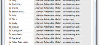
 Notice parts and assemblies have different icons, and also notice that virtual components (shown in this image under the Engine in the Pathfinder) are different from the real components (shown at the bottom of the Pathfinder as Part1.par and Fourbar.asm)
If you start in an existing assembly, the Structure Editor will read the existing structure and allow you to add to it. You can also delete components.
You can create a combination of real and virtual components, which is very nice.
To make the Virtual Components into “real” components (that have files saved on a hard drive), you can use the Publish Virtual Components tool.
 The publish tools are really nice, they allow you to specify the path for each individual component, and also you can specify templates to be used for each file as well. But there is only one option for Publish, and that’s to publish all the virtual components that exist at the time. You can have virtual items like paint, glue, grease, mentioned earlier, but if they exist when you publish, they will stop being virtual. To work around this, you might add items that you want to remain virtual only after all of your other components have been
  added. A good enhancement request for this area of the software might be a selective publish option.
What I’ve shown to this point is just a quick introduction to the Virtual Component tool, and only the simplest way to use Virtual Components. There is a lot more to show, and I’m going to save that for a second post on this topic. In my next post, I’ll talk about how you can use sketches and 2D block functionality to seriously accelerate your assembly design process.


Comments