Solid Edge Tips and Tricks #7
Is there a way to find out what all of the two-letter codes are for callouts?
 Yes. Go to the Callout command and select the Property Text button from the Callout Properties dialog. Now click on the “Symbols and Values” button down near the bottom of the Property Text dialog. This will bring up a third dialog which has all of the two-letter codes sorted into groups. Expand the grouping tree to find the codes you might be looking for.
Can I create a user-defined material with its own density?
 Yes, you can create a new material in the Solid Edge Material Table (Application menu> Properties> Material Table) and assign user-defined properties and values to it. To add a material, right click on the material family folder (such as Steel, Iron, etc.) and select New Material from the list. You can also copy an existing material from the list and paste it into the folder. Make sure to give it a new name when you do this, and also make sure to change the appropriate individual properties. These properties will then be assigned to the part once they are applied to the model.
Why am I unable to rotate a Section View pulled from a broken view?
There are a few factors which play into the ability to rotate a view. First, the view must be unaligned from the view from which it was pulled. Second, you must undo the “Show broken view” button. Finally, the break lines must be deleted from the view. After this, the Section View will rotate. After the rotation, you can recreate the break lines.
How can I change the edge color of a part in a drawing view?
Right mouse click on the Drawing View, select Properties, click on the Display tab, select the part, and select a visible edge style which has been configured with the desired color.

How to hide individual edges in a drawing view?
 Drawing View edges can be individually hidden by the Hide Edges command. The command is located in the Ribbon, on the Home tab, Edges group. Just click the edges to be removed from the drawing and they will not be displayed anymore.
Why does selecting “Use Designed Assembly” only toggle the first level?
Prior to ST7, if you selected “Use Designed Assembly” all subassemblies that were simplified would be toggled to designed, no matter how many levels there were. In ST7 only the first level subassembly will be affected. If you want to toggle all levels you can press and hold the [CTRL] key while selecting the “Use Designed Assembly” command.
Why can’t I select a region for the cross section curve in ST6 in a synchronous helical cutout command?
You have to select each edge of the closed cross section individually AND also the axis in one single step to make this work. Improved in ST7 by letting you select a region for cross section and axis in two separate steps.
Why am I seeing my thread feature in a front view but not in the right view of the assembly drawing?
 The problem seemed to be because of the default tolerance setting for “thread axis tolerance”. But we were able to override this and use a value of .01 deg. After this when we updated the view the thread showed up on the right view. You can find this setting in “Drawing View Properties/Advanced tab”. Update the view after overriding the default tolerance.
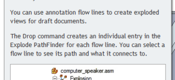
What are the advantages of dropping flow lines and having annotation flow lines?
 Annotation flow lines have the full range of edit. They are not used for exploded animations, but are designed for making drawings. You can draw and modify them to get what is needed in the drawing view. Drop is only available in ERA (on the Tools tab), which is only available in assemblies.


Comments