Solid Edge Tips and Tricks #3
How do I get an underline on a Drawing View Caption?
Go to the View Properties dialog and the Caption tab. In the Format box, check the Separator option.

Why can’t I zoom in & out using my scroll wheel mouse in draft?
This behavior can be caused by having scroll bars turned on. To resolve, go to Application Button -> Solid Edge Options -> View. Uncheck the Horizontal scroll bar and Vertical scroll bar check boxes. You should now be able to zoom in & out using your scroll wheel mouse.

How can I place reference text in draft that won’t display in prints?
This type of text can be placed outside of the drawing sheet boundary.

What could be causing our long file open times from non-managed Windows server?
We often run into performance and install issues with customers using Symantec virus tools.
What is the maximum length of a file name in Solid Edge?
The maximum length is 255 characters, including the full path.

How do I create a dimension style for dual unit dimensions?
Go to View -> Styles -> Dimension -> New -> give the new style a name -> Secondary Units -> check Dual Units and other desired options -> OK -> Apply. Go to the dimension command and see that the new style will be listed in the drop down list of available dimension styles.

How can I turn off all coordinate systems in my assembly?
 Right click in a blank space in your graphics windows and select “Show/Hide All Component”. Check the Hide box next to Coordinate Systems in the dialog and click OK.
How can I create a custom frame cross section for frames in assembly?
First you have to create a part with a closed sketch or profile with the desired cross section. After this run the ‘FrameComponentUtility.exe’ found in ‘Frames’ folder in the product to define the origin point and the X-direction of the profile, once completed the part can be used in frames environment.
How do you modify an existing profile on an Ordered Flange in sheet metal?
This can be done after the Flange is placed, by Edit Definition on the flange, then click the Edit Profile button. Also you can do this prior to clicking Finish, during creation of the flange. It is imperative that while modifying the flange’s profile, that you must make sure each end of the profile MUST be connected to the Neutral Factor line (dashed) approximately 1/3 the sheet metal thickness of the metal of the part. If this is not done, you’ll not be able to get out of the profile step.
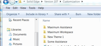
How do you copy the radial menu definition from one machine to another? Where is the definition of the radial menu stored?
 User interface themes, which contain any edits to the UI, are located at C:users[username]AppDataRoamingUnigraphics SolutionsSolid EdgeVersion 107Customization
What could be preventing me from being able to export a specific part file out to STL format?
Most commonly it is the result of problems with the geometry you are trying to export. For example, imported STEP files sometimes have construction surfaces and other geometry in the file that will need to be cleaned up in order to re-export cleanly. You can utilize Geometry Inspector to help identify problems with existing geometry.

Comments