Solid Edge Adjustable Parts
The documentation group for just about any software rarely gets good news in public, but there are a couple of things I want to point out before moving forward with the rest of this article. The first is just to reiterate that putting the Help documentation online I think is a big move forward. Just being able to share a link and send someone to a specific page in the Help is very, well, helpful.
The second thing I want to point out is that I was able to do most of my research for this article just reading the Help (75%) and playing with examples (25%). Not all topics are as easy to research as this one has been, but I found the PDF for Adjustable Parts and Assemblies to be very clear and well written.
Adjustable Parts in Solid Edge are parts that allow you to define variables that can be adjusted when the part is put into an assembly. Parts that flex in a way such that you can simulate the change by changing a dimension, like a spring, or an O-ring. Just to be clear, this does not mean that you can move a linkage and watch a spring expand and contract live. It means you move your assembly to a particular position, and the spring will expand or contract to fit.
SolidWorks doesn’t really have a direct equivalent for this, although it has elements of configurations, in-context, and flexible subassemblies. You can create the same effect in Works, but you have to do it manually. Solid Edge has an actual tool that helps you set it up, making it a lot easier and more reliable.

For this exercise, I’m using a toggle clamp assembly, which is attached to this article so you can download it. This is a typical four bar link mechanism.The arm on the right will establish the length of a simplified spring. Let’s go over how the simplified spring was made first.
 The simplified spring is just a cylinder extruded up to a plane. It is all created in Ordered features, but I believe that if you have appropriate PMI you can also create adjustable parts from Synchronous models as well. It turns out that you could use a cylinder with any end condition, it doesn’t have to go up to a plane. It could have been a blind extrusion. The main thing is that you’ve got a dimension. In this case, I’m going to change the 3.000 dimension in the assembly.
 To make this into an Adjustable Part, click on the Tools > Assistants > Adjustable Part icon. Make sure that the dimension you want to drive in the assembly is showing on the part.
Click on the dimension you want to drive, and its name should show up in the Variable Name box as shown above. If you want to control the name of the variable, you can go to the Variables group still on the Tools tab, and use the Variables tool to change the name.
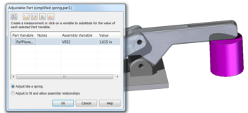
Once you have all this done, and have saved the part, flip back to the assembly using Ctrl-Tab, and right click on the simplified spring in the assembly. There will be a choice for Simplified/Adjustable. Select Adjustable from the flyout list. This should show you the same Adjustable Part dialog that you saw in the part, with a few extra measurement icons on it.

There may be better ways to do this, but here’s how I did it. I selected the Measure NormalDistance option, and selected the bottom of the base plate, then turned the display to wireframe, and selected one of the endpoints on the Arm part out at the end where it touches the spring. This shows Solid Edge the measurement in the assembly that you want to match the measurement you identified on the part. So when they change, they will change together (not dynamically while dragging, but after a move).
That’s all that there is to the set up.
You can have multiple occurrences (what Works calls “instances”) of the spring. Some might not be affected, some might be affected by something else. This doesn’t use Solid Edge’s Family of Parts, everything is kept within a single part file. The adjustable bodies, however, are stored in the assembly file. The online PDF on this topic mentioned earlier is a great additional resource for step-by-step tutorials on these tools.

So adjustable parts are fairly simple to set up and implement once you know how to do it. You have to identify them in the part file, and then again in the assembly. Remember that you can control individual occurrences if you have more than one of the same adjustable part in an assembly.
The next article on Wednesday will show how to make this assembly into an Adjustable assembly.


Comments