Special Traits of the Bluesurf
We’ve talked before about NURBS surfaces always wanting to be four-sided, much like a piece of fabric made from threads running perpendicular to one another. It can be stretched and pulled, but it also has a limit. But we all know that not all faces on a CAD model are nice and neat four-sided faces. Fortunately, just like a shirt isn’t only made of virgin bolts of material right off the loom, you can also trim a surface to any shape you want.
So now let’s talk about how each of the interpolated surface types is made. Understanding how the surface works will help you understand which feature to select for a given situation.
 Bluesurf
The Solid Edge Bluesurf works like a loft (or a Boundary surface in ‘Works). For the input, you can use 2D or 3D sketches, edges, or curves. When you start a new project, you are often working with sketches, but as there is more geometry to work from, you often use edges in projects that are further along the process.
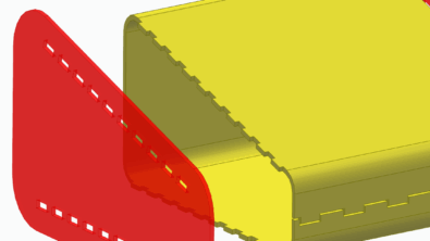
A Bluesurf can accept roughly parallel curves, or curves arranged like a letter F, E, T, L, H, A, X (refer to the image below). Notice that of these, the letter A would only create a 3 sided patch. This is the dreaded “degenerate surface”, where the fourth side exists as a zero-length  member.
The image to the right shows a set of curves that can be used as sections and guides in a bluesurf feature. It might take some imagination to see different arrangements of the curves as representing letters, but this is one of the tools I use to visualize how the features are set up.
While we’re talking about the image with the mesh of curves, we need to also talk about a couple of tools that Solid Edge that helps you make things like this that you might not find in other software.
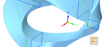
For example, when you are sketching on one plane, and another curve intersects that plane, Solid Edge gives you visual feedback and allows you to snap to that intersection.In the image below, I’m sketching the red dashed curve, and the orange highlighted curve intersects the plane I’m sketching on at the red X points. Notice the cursor feedback that Solid Edge gives me at the Pierce Point. This is great Solid Edge functionality that is very useful in this kind of situation.

In the Solid Edge interface, curves in one direction are called “Cross Section” and in the other direction are called “Guide Curve”. It turns out that it doesn’t really matter which is which, since the directions are treated equally by the feature. So a Bluesurf feature that uses an “L” arrangement of curves, the vertical curve could be either cross section or guide curve, and the horizontal curve would just be the remaining direction.
This incredible flexibility of the Bluesurf being able to use such a wide range of curve arrangements really makes Bluesurf the go-to surface type for most shapes.
There are also some special situations that you might not have considered, and may not run into every day:
Loft open loop to point (cone). If you loft from a circle to a point, you get a cone. But did you know you can also change the end condition at the point to Parallel To Section to make a blunted cone? This can be useful in a lot of situations, since making a rounded shape like this with other tools is pretty difficult.


Loft closed loop to open loop (chisel). You can loft from a closed loop to an open loop as long as the closed loop has more than one element. Which is to say you can’t loft from a circle, ellipse, or closed loop spline. This is something you can’t do in other software I’ve used.

Closed loop

Closed loop where start/end are inverted (moebius). This is again something you can’t do in other software I’ve used. Is this useful in itself? Maybe. Are limitations useful? No. When you are working through a set of options to create geometry, you don’t need your software telling you which shapes you should or shouldn’t be able to make. You can take this flexible concept and achieve a real world requirement. The green dotted lines connect the corner closest to which each closed loop was selected. This enables you to define the twist of a Bluesurf feature as you select the sections. Very nice.

If you want to work through some of the examples I’ve shown in this blog post, please download the attached file. It is in Solid Edge ST7 format.
Next time we’ll talk about sweeps.