5 Tips to Better Productivity in Drawings for Solid Edge
3D models work well to help us visualize products. A model provides a sense of space and depth; you can orbit around it, or spin it around. You can make it transparent or colorful, and even render it so that it’s virtually indistinguishable at first glance from a photograph.
While all of that is useful, when it comes to manufacturing, drawings are still king. Nearly all companies rely on drawings to communicate important manufacturing information that is essential to accurately produce the product or part. This information includes size, material, features, locations of features, and tolerances. Drawings also serve as legal documentation to ensure that parts are made “to spec” and that there is a paper trail (pun intended) should any issues arise in the future.
For top-notch drawings that are easy to create, we’ve put together some useful guidelines to help you achieve better productivity in Solid Edge. You can also download our white paper to learn more helpful tricks.
- Templates
Think of the template as the foundation to your drawing. By taking the time to set up a great template, you will not only guarantee great drawings, you will also save yourself time down the road. The template consists of a title block with the company name and logo, along with any information specific to the organization such as standard tolerances, materials, treatments, authors and checkers, and most importantly, titles and part numbers. While title blocks do vary in appearance from one company to another, they contain the same relevant information that pertains to the part portrayed in the drawing.
The best method is to have as many of these fields as possible automatically populate based on “properties” from the model. This means that when you assign the model properties such as material, part number, treatment, etc., those respective fields on the drawing will automatically populate as soon as said part is referenced in a drawing view (whatever the first view placed is). Assigning these properties in the part and having it populate fields in the drawing will save time that could be better spent elsewhere.
Templates also will contain the formatting and “style” for the drawing. The templates font, font size, dimension style, view style, and captions appearance are all contained within the template. Taking a good day or two to fully define a complete set of templates can increase productivity so that you don’t have to change all of the settings each time you start a new drawing. We recommend setting up a template for all of the various kinds of documents that are created within Solid Edge—manufacturing drawings, work instruction sheets, and manuals are a few examples.
Quicksheets are yet another drawing template in Solid Edge that you can use to save time. Quicksheets are templates with predefined views, captions, notes, etc. These are great for standard parts to create orthographic projections (multiview drawings) of parts that always require the same views. When a Quicksheet is employed, its quick part specification as to which part will be depicted, and all the views are automatically generated; just add dimensions and any relevant notes to that part. All green text in this title block is populated by “File Properties.” Title blocks can pull in hundreds of variables of property text depending on your company’s needs.
 - Custom Views and Configurations
Custom Views: Custom Views are especially useful when working with assemblies. For more complex assemblies, the main principle views or generic isometric, dimetric views are not always enough. They may not get just the right angle to properly depict all of the parts in the assembly, so make sure to do a bit of ground work before throwing the assembly into a drawing. Orbit around the assembly to get it into the right orientation, then select View Orientation at the bottom right of the workspace and click on Save Current View. This will save a “camera view” that is selectable in the Drawing View Wizard as custom view.Configurations: Configurations allow you to show/hide parts by selecting a check box in the parts tree. Once the desired parts are shown, you can save the view by clicking on the configuration manager to set up a new configuration. This, too, will become a selectable item in the Drawing View Wizard. What’s even more powerful is that BOMs can be generated for configuration specific items.
.png") View configurations allow you to easily create selectable views at the drawing level and create view specific BOMs.
View configurations allow you to easily create selectable views at the drawing level and create view specific BOMs. - Retrieve Dimensions
Retrieve Dimensions is a very powerful timesaving tool. With it, you can pull dimensions used in the modeling phase right into the drawing in the view that you assign them. Usually dimensions that are placed in the model are important design-intent tidbits that can be used as manufacturing dimensions. With this method, you will only have to enter those dimensions once!
Retrieve Dimensions is not an easy button or “auto-dimension” tool. It will only pull in dimensions that YOU placed, and it will pull in dimensions that are normal to the view that they are being placed in—meaning if you placed a circle/hole normal to the top view, it will not retrieve that dimension in the side view(s). While retrieving dimensions is a quick way to get design dimensions, a little cleanup may be required as it will retrieve ALL dimensions that can be seen in the view you applied them to.
As the saying goes, “time is money!” Nothing saves more time than reducing drawing time by pulling in dimensions.
.png") Retrieving model dimensions is a fast and easy way to capture dimensional design intent!
Retrieving model dimensions is a fast and easy way to capture dimensional design intent!.png")
- Shortcut Keys
Shortcut keys are another time-cutting tip you should take advantage of when using Solid Edge.
We are not talking about AutoCAD type hotkeys. The two main keys we are referring to are the Alt key and the Ctrl key. With the quick press of a button, a view can be copied, a leader can be reattached, or a dimension can reference another point. ]Let’s break down what the two keys do in drawing mode:
Ctrl: The control key is a quick copy tool. Rather than using the right mouse button to copy and paste or using a Windows command such as CTRL C + CTRL V, you can simply click on a view, hold down CTRL and left-mouse click drag the view to copy it! At that point, you can right-click on the view and select View Properties to change the view to a different configuration, for instance.
Alt: The Alt key is a modifier tool that allows you to do a number of things in drawing mode. Most of these deal with dimensions or notes.
Alt-Left mouse click…
…on a leader will add a jog to a leader
…drag on a balloon leader arrow will allow you to reattach it to another entity
…drag on dimension reference point will allow you to redefine its reference point
…drag on a leader where it connects to a callout will allow you to change the location of its attachment to the callout.
…drag on a dimension line in a dimension set (see point 5) will allow you to move just that dimension without moving the entire set.
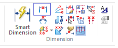
Another lesser-known key in dimensioning is the “a” key. When dimensioning an arc in Solid Edge, clicking on “a” after selecting the arc using Smart Dimension will toggle between the radius, arc length, and arc angle.
.jpg")
- Distance Between
Speaking from experience, “Smart Dimension” is usually the go-to dimension tool for CAD users, as it easily detects which line you may want to dimension. The problem with Smart Dimension is that you must constantly re-select it, or press ENTER and redo the command. Say, for instance, you want a stack dimension (baseline dimension), you will repeat placing a dimension, then redo the command to place the next dimension.
Using the “Distance Between” command allows you to place the first dimension and, from there, choose a path as to chain dimension or stack dimension (or right click to end the command and start it again elsewhere). Once the first dimension is placed, going to either side of the dimension and clicking on the next adjacent point will bring a preview of a chain dimension; move the mouse up or down slightly to see a preview of a stack dimension. Once you left click to accept either/or, that is the style it will use for that set of dimensions (until you right click or hit the ESC key to end the series).
Once a set of dimensions has been placed, you can move the entire set at once by dragging any one of the dimensions!Using Distance Between allows you to easily stack or chain dimensions together and set up a dimension “set” that can be arranged in unison.
If you were to use even just one or two of these tricks, you can drastically increase your drawing productivity in Solid Edge. Once you master all of the above tips, you will be creating complex drawings in no time! Download the white paper on CAD drawing top techniques for more tips.


Comments
Leave a Reply
You must be logged in to post a comment.
How can we get graphical connection to part info to auto fill with clicking on the part to get a link?