3D Sketching: The future of sketching in CAD
In mechanical CAD, sketching is the basis for creating 3D models. Now, there are exceptions e.g. using synchronous technology in Solid Edge, you may not need sketching at all if the model is made up of primitive shapes like box, cylinder and sphere. But for complex models, there is no alternative to features based on sketching profiles.
While 2D sketching can be used to create extrusions, holes, paths and other features, its restriction of drawing on a single plane is cumbersome, when creating some complex shapes. We always see and create things in 3D then why restrict us to sketching in 2D? The 3D pen from 3Doodler is a result of this fascination of creating things in 3D.
3D Sketching in Solid Edge is similar to drawing using the 3D Pen. Solid Edge includes set of 3D sketching tools to ease the process of creating sketches in 3D dimensions. Just take the example of the model below. See the number of 2D and 3D Sketches needed to create the model.

This article will try to give a brief overview of 3D Sketching functionality in Solid Edge. As you must know 2D Sketching, we will be comparing 3D Sketching with it.
3D Sketching in Solid Edge
3D Sketching is not new to Solid Edge. Since 3D Sketching is mostly needed for creating paths, it had been in routing applications like piping and frames from years called Segment commands. But it was a limited set of commands.
In Solid Edge ST7, 3D Sketching was introduced in Part, Sheet metal, Assembly and routing environments. Similar to 2D Sketching, 3D Sketching commands are available in a separate tab in Synchronous and in an environment for Ordered.
 Ordered
3D Sketching display
3D Sketches look similar to 2D Sketch but the style of 3D Sketch is different. 3D Sketch use the Edges properties from the Face Styles.

Pathfinder display
In Synchronous, all 3D Sketch elements are added to the active 3D Sketch. An active 3D Sketch is displayed with a pencil icon in pathfinder.

If a new sketch is required, you can use the ‘New 3D Sketch’ command which will create a new sketch and make it active. A 3D Sketch can be made active by using the ‘Activate’ command in context menu of that node in pathfinder.
In Ordered and Assembly, pathfinder display and behavior for 3D Sketches is similar to 2D Sketches, just that you do not need to select a plane for creating a new 3D Sketch.

Drawing 3D Sketches
 3D Sketch draw commands
If you observe, the 3D Sketching commands are similar to that of 2D Sketching. But the difference is in the way you draw them. Unlike 2D Sketching, 3D Sketching does not need a plane to draw. You can directly start drawing in space and use the triad to orient the sketch elements.

Since 3D Sketches will mostly be used for creating paths, be it for routing or sweeping, there is a special command called Routing Path in the Draw group. This is added in Solid Edge ST10. It is similar to the PathXpress command in routing applications. You can get more details about this and other enhancements done in ST10 here.
The triad in 3D Sketch is similar to that of Keypoint Curve command. But the additional thing in 3D Sketch is that the triad can be oriented to any coordinate system present in the model. This can be done by the ‘Relative to’ option on the command bar of 3D Sketch elements. The Coordinate system in use is highlighted.

3D Sketch elements can be locked to planes or faces, locked to keypoints, locked to axes, or randomly drawn in 3D space.
You can either use the triad to lock the sketch to axis or planes or use the keyboard accelerators.
- z- Lock to triad axis. It also toggles between the 3 axes.
- For locking to any other plane use the Lock Sketch Plane option from the command bar.

- x- Locks to a triad plane. It also toggles between the 3 planes.
- s- Locks to a highlighted edge.
3D Sketching Intellisketch
Similar to Intellisketch for 2D Sketching, 3D Intellisketch is used to control what keypoints can be located and what constraints it can create when creating 3D Sketch elements. But one additional option in 3D Intellisketch is Project Keypoint, by which you can select a keypoint at its place or project it on a sketch plane.


3D Sketch Relationships and dimensioning

The 3D Sketch relationships are similar to 2D Sketch, but they work only on 3D Sketches. The relationships that are unique to 3D Sketch are the Coaxial  and On Plane
 .
.
The Coaxial makes the 3D Sketch coaxial to circular objects and the On Plane makes the 3D Sketch coplanar to a reference plane or a planar face.
The existing dimensions commands can be used to dimension 3D Sketches. Note that True dimension will always be placed by default for 3D sketches. You can create projected dimensions using various options available in the dimensions command.

Editing 3D Sketches
Since 3D Sketches are not always contained to a plane, editing or modifying them in 3D space can be tricky as we may sometimes not see the true length or shape of the 3D element. Other than this aspect, editing of the 3D Sketch elements is similar to 2D Sketch elements. You can use the command bar for modifying dimensions, use the edit handles or use the Move command using the steering wheel. In all the cases the 3D relationships will be honored.
 Editing single element
 Editing multiple elements
 Editing using handle points
3D Sketching usage
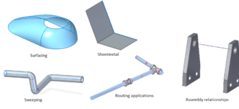
Almost all commands that require a Sketch/Profile can use 3D Sketches. Following are some of the examples.
Part – Extrude, Sweep, Extruded Surface, BlueSurf, Bounded etc.
Sheet metal – Tab, Contour Flange, Dimple etc.
Assembly – Assembly relationship commands, Drag and Move components, Assembly feature commands etc.
Routing – Tube, Piping Route, Frame etc.

So that was a quick overview of 3D Sketching in Solid Edge.
More to come! We are listening!
We will continue to enhance 3D sketching in future as we are listening to your requests through ER’s and community posts. So do put your comments and queries to this post! Happy 3D Sketching!!


Comments