25 Uses of the Scroll Wheel in Solid Edge
If you are using the scroll wheel on the mouse in Solid Edge for merely zooming or rotating the view then this article is for you.
Even if you know a few more uses of the scroll wheel in Solid Edge, you will still be amazed to discover how much more the tiny wheel can accomplish.
So keep scrolling…
Direction Reversal
In any of the 3D environments – Part, Assembly or Sheetmetal – turning the scroll wheel zooms the model.
In the process of turning the wheel ahead the finger moves ‘away’ giving the feeling that the model too is moving away, which in reality is simply zooming out of the view.
Not many other CAD programs have the same notion. For some of them, turning the scroll wheel ahead or ‘up’ gives a sense of getting up-close with the model which is zooming in to the view.
So perhaps to accommodate such users migrating from other CAD systems, a setting was introduced where the default scroll wheel behavior could be reversed. This setting can be toggled in the Options dialog under the View tab:

Key Combinations
Scroll wheel press-and-drag rotates the view 
Keep the Shift key pressed and press-and-drag the wheel to Pan 
Keep the Control key pressed and press-and-drag the wheel to zoom  in a much smoother way as opposed to the jerky or incremental zoom with each tick of the scroll wheel.
Keep the Alt key pressed and press-and-drag the wheel to start the Zoom Area  command.
Additionally keeping the Control key pressed allows zooming in an area centered around the drag start point.
The differences are illustrated below:

 Finally, double-clicking the scroll wheel will Zoom Fit
  the view.
Perspective On-the-Fly
Keep the Control and Shift keys pressed together and turn the scroll wheel to get a perspective added to your view with 12 levels of fine tuning.

This is significant compared to the View Overrides dialog which allows only 3 presets.

Scroll Wheel in the 2D Environment
In the Draft environment, scrolling the mouse wheel will zoom in and out but this behavior can be changed by enabling the scroll bars from the Options dialog.
The view will then pan instead of zooming on turning the mouse wheel.

 Note: The option to reverse the zoom direction is available in the Draft environment too.
Zoom Fit Behavior
Double-clicking the scroll wheel Zoom Fits in the Draft environment as well and here the background sheet plays an important role.
By default, double-clicking the scroll wheel will Zoom Fit the Background sheet and the drawing objects or drawing views placed outside the sheet boundaries as shown in the image below:

Keep the Shift key pressed and double-click the wheel in the Draft environment to Zoom Fit only the drawing objects and drawing views without any consideration for the background sheet as shown below:

Keep the Control key pressed and double-click the wheel in the Draft environment to Zoom Fit only the background sheet as shown below:

Just as in the 3D environments,
- Keeping the Control Key pressed, scroll wheel press-and-drag Zooms In/Out
 the sheet.
 - Alt + wheel drag window is Zoom Area
 in the Draft environment too.
Scroll Wheel in the Ribbon and QAT
Scrolling the mouse wheel with the cursor over the ribbon bar or the Solid Edge title bar or the Quick Access Toolbar changes the active tab on the ribbon bar.
So this is a nice lazy way to access a tab without having to actually turn your wrist and click a ribbon tab ![]() Give it a try today!
Give it a try today!

Scroll Wheel in the Pathfinders
Turn the mouse wheel over the Assembly Pathfinder to scroll the components. Be careful with the mouse pointer location. If the mouse pointer is right on a component name, the Pathfinder scrolls.
If the mouse pointer is inside the Pathfinder region but not on a component name, the model zooms in/out since this implies the mouse pointer is in the graphics area.

The key here is if the component is highlighted, the Pathfinder scrolls, else the model zooms in/out.
Scroll Wheel on the File Tabs
Simply click the scroll wheel over a file tab to close the document or a document window.

Modifying Dimensions with the Scroll Wheel
When you click a dimension on a synchronous model, the dimension value appears in a popup text box right at the cursor so you can continue turning the scroll wheel on the mouse to change the selected dimension which in turn updates the model in real time.
Outside the dimension text box, scrolling zooms in/out the on the model. You can override this behavior by keeping the Control key pressed when scrolling.
This setting can, however, be changed from the Solid Edge Options dialog and the video below illustrates both the modes. Pay careful attention as you may have to watch the video several times to fully understand the behavior.
Controlling Model Rotation with the Scroll wheel
Another interesting use of the scroll wheel in the 3D environments is in rotation.
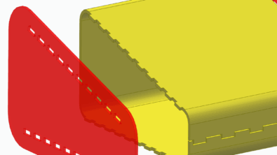
With no command active i.e. with the Select tool selected, press the scroll wheel once. The rectangle attached to the lower side of the cursor disappears.

At this moment, hover the cursor over the model to highlight a pink vertex or edge and click i.e. left mouse click to set the selected vertex or edge as the point or axis of rotation.
After this press and drag the middle mouse button or the scroll wheel to rotate the model about the selected point or axis.
The image above shows the cursor when the model is rotated about the selected vertex and the edge.
This setting persists across modeling commands meaning Solid Edge remembers the point or axis and the next time you press-and-drag the wheel, the model rotates about the set point/axis.
If you find the vertex/edge stuck, simply click the wheel once in an empty area. Now press-and-drag the wheel and the model rotates freely.
Also, it is not necessary to pick only an edge or vertex. You may middle-mouse-click on a face and Solid Edge will pick a point on the face for the rotation point
Scroll Wheel in the Assembly Preview Area
In the Preview area of the Parts Library pane in the assembly environment, if you select a part and press-and-drag the scroll wheel to adjust the orientation of the preview, then drag-dropping the part into the assembly places it in the assembly in the same orientation as that in the preview.
This can save a lot of hassle later when applying assembly relationships since the part is placed into the assembly in the closest orientation as its final orientation in the assembly.

Nevertheless, nothing should stop you from scrolling the mouse wheel in any part of the Solid Edge UI, some of which, but not limited to, could be – the Style Palette, the Configurations drop-down and the Reports dialog in the assembly environment, Parts List dialog – Data tab, Recent Files List, Options Dialog, etc. and so on.

Who knows what hidden tip you might bump into.
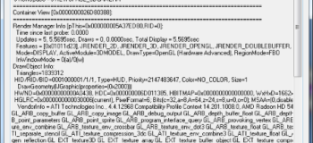
For example, I am not sure what purpose this information serves so you can consider it an Easter egg inside Solid Edge and reveal it by keeping the Control and Alt keys pressed together and double-clicking the mouse-middle-button i.e. double-click the wheel to display the View Probe Info dialog which furnishes loads of seemingly important looking graphics card and related information, most of which would be Chinese to a casual user.

If you discover or know a hip tip on using the scroll wheel in Solid Edge, do not forget to mention it in comments.
Until then, keep scrolling…
Tushar Suradkar
Solid Edge User Group on FaceBook: