Response Surface and Sequential Optimisation of a Heatsink Using FloTHERM. Part 1 – Defining a Design Space
Heatsinks are a very common method of aiding the transfer of heat from a source (e.g. IC die) to a cooler ambient. More ‘area extenders’ than heat sinks, they spread the heat to a wider solid/fluid interface whereupon it is convected and radiated away. The more effective they are at getting the heat out, the lower the temperature rise at the heat source. They’re also often not cheap. Designing (or selecting) one that fulfills its thermal obligations but isn’t over engineered is a frequent activity of a thermal design engineer. FloTHERM is packed with capabilities to apply simulation to this design challenge. This series will step through each stage, getting our FloTHERM hands dirty along the way.
“There’s little or no value in a single simulation” was one of the first things I learned in my career. If it’s late in the design process, everything’s fixed and you’re rubber stamping the design by simulating its intended behaviour, then sure, do a single simulation. Bit late in the day if it pops up any unexpected results though. Much better to apply simulation early, at the architectural / conceptual stage of the design process. Try out various engineering concepts, balance conflicting requirements, explore the available design space. A stitch in time saves 9.
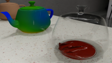
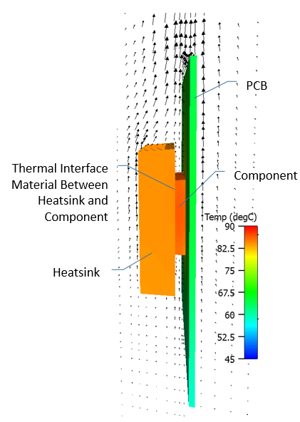 Let’s consider a simple set up, a single component on a PCB voucher. An Aluminium extruded plate fin heatsink is placed on top of the component with a thermal interface material at the component/heatsink interface (to assure a good solid-solid contact).
The component dissipates 4W, the assembly is vertically orientated, cooled by natural convection (no fans) and in a 45 degC ambient. Air moves vertically through the heatsink fin channels, due to buoyancy.
.
.
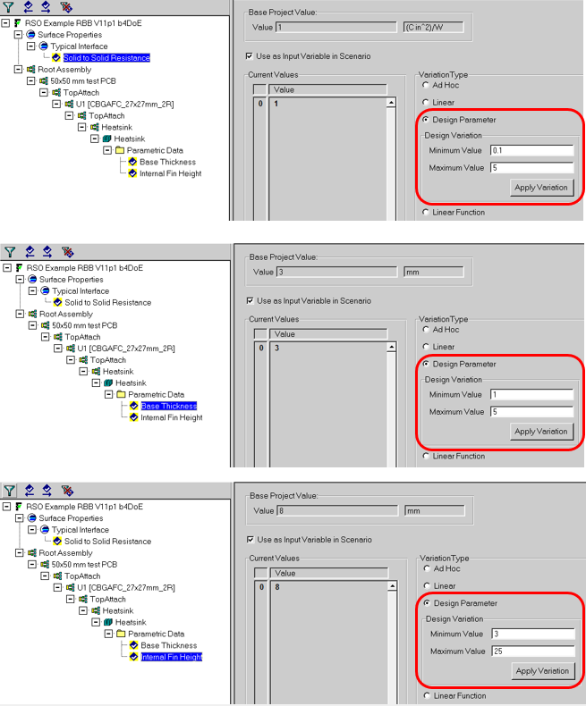
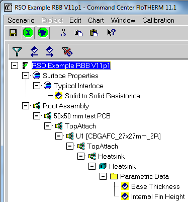 FloTHERM’s Command Center application window allows parametric investigations to be conducted on a base case model. From manually defined ‘what if’ variations through to fully automated optimisation studies. In this case we need to define what parameters are to be varied and by how much. By doing this we set the design space to be explored. We’ll vary the TIM2 interface resistance (0.1 (expensive) to 5 (cheap) DegCin^2/W), the heatsink base thickness (1 to 5 mm) and the heatsink fin height (3 to 25 mm). (Just about) Any model setting that can be manually adjusted in FloTHERM can be included in a Command Center parametric study. This is what it looks like in Command Center:
.
.
That’s the necessary (but not so interesting) setting up of the design space done! Next I’ll show how FloTHERM’s integrated design of experiments feature can be used to populate the design space with a user defined number of combinations of these 3 parameters.
26th January 2016, Ross-on-Wye