Where’s the Best Place to Put a Radiator in a Room? Part 4: Premature Simulation
One thing the Mechanical Analysis Division is not guilty of is vendor hubris. Despite the passion we have about our CFD based simulation solutions we know our place, especially in terms of where best to apply our solutions throughout the design process. CFD is a very powerful tool to predict 3D heat air flow and heat transfer but it certainly isn’t the only approach. As is common in both electronics cooling and built environment design, abstracting the topology of a design down to a simple network of connections between key parts allows for very quick estimates made as to its performance. Often the earliest type of simulation based approach, such methods are often defined in a spreadsheet to allow a first order accurate design starting point to be identified. After all, who on earth would detail a design to the 3D extent whereby a CFD simulation could be conducted without first confirming that, for example, the size of the radiator was correct. Who indeed…
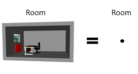 Most designs lend themselves to being compartmentalised, reduced to a series of objects with connections between them. Obvious for electrical and piping systems which by their nature have a series of 1D connections between node points. Function dictates that occupied spaces are separated by partition walls, turning them into rooms. We can then consider a room to be a single point that we’re interested in.
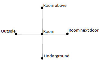 From a heat transfer (and thus thermal comfort) perspective our room is connected to its surroundings. We can construct a real simple network to show those connections. We then assume what the temperature of those surrounding nodes are. Outside = 0 degC (or as we call that in the UK, ‘late summer’), neighbouring rooms lets say are at 20degC, undergound somewhere in between. For our room we will set it at the desired temperature, typically 22degC.
To work out how much heat would need to be put into our room to support these temperatures (differences), and thus how big a radiator would be required, we need to know how well connected the room is to its neighbouring surroundings. In the built environment world U-Values are used. Numbers that represent how difficult heat finds it to go ‘through’ that U-Value. These values are quoted by suppliers to the building industry to characterise things like windows, expanded foam insulation etc. and are quoted by building regulations as maximum values for say internal and external walls. For now, considering my design already ‘exists’, I’ve backed out the U-Values of the walls etc from the settings I put into FloVENT originally (warning, about to get a bit techy: U value is the inverse of the sum of all resistances the heat experiences, boundary layer+radiative exchange then conductive resistance then the boundary layer+radiative exchange on the other side, half input, half predicted by CFD). Then it’s simply a case of working out how many Watts goes out of the room using the following table:
 2549 Watts to maintain these temperature values. Or in other words, this is how much power a radiator would have to provide to maintain the room at 22degC in its prescribed surroundings.
[Note to anyone with any experience of U-Values: yes, you are right, with values so big this room would never get past the building inspector nowadays. Radiator sizing isn’t the only thing I’m good at getting wrong when designing built environments…]
[Note to anyone with electronics cooling experience: yes, this is looking very similar to the use of thermal resistance metrics in the prediction of operating temperature, or maximum allowable power in this case]
How much power was the original hastily-defined-with-not-much-forethought radiator giving off in the FloVENT model? I’d defined it at a fixed temperature of 70degC then from the simulation had FloVENT tell me the total heat loss from it was:
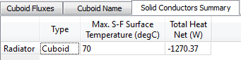
[Tip for FloVENT (and FloTHERM) users: select columns or rows in Tables, right mouse click and select ‘hide unselected rows/columns’ to get the above, or launch Excel from Tables and have the selected data pushed directly into Excel]
The original radiator gave out (-ve heat gain) 1270W. No wonder there were so many people dissatisfied, regardless of its location, considering nearly twice that power would be required to get the desired 22 degC. So how big should a radiator be to give off ~2.5kW? Instead of looking into Nusselt number correlations for fixed temperature vertical surfaces I decided to Google instead for “Radiator Power Output” and found this handy DIY reference page with a nice table that related power output to radiator size. From that figured out how big the radiator should have been (it was indeed about twice the size than I’d set before), set that and re-simulated in FloVENT.
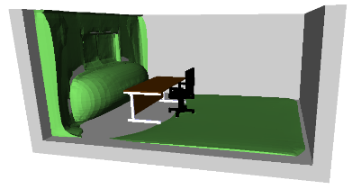 Let’s check out the 25% PPD (percentage people dissatisfied) blanket shape. Hardly anywhere would so many people be dissatisfied now. In fact, taking the average over the whole room, only 9% of the space would result in people complaining compared to nearly 19% before, with the radiator in the same place.
So, position isn’t always the critical factor, size is often more important (so I’ve been told on one or two occasions).
Next time I’ll explain how we’ve used this application as an interview question for many years and how now I’m persona non-grata for giving away the answers…
9th August 2012 Ross-on-Wye