Underfloor Electric Heating. Part I: In by Christmas
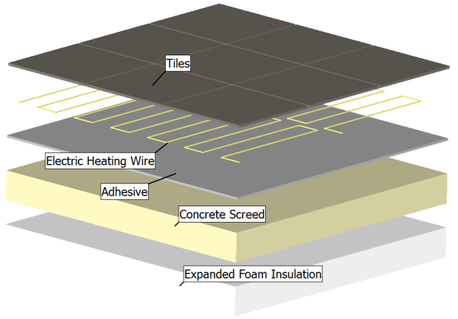
It’s been over two years since the foundations went in for the extension we’re building on our house. In that time I’ve come to respect and somewhat rely on glib phrases such as “Good things come to those who wait” and “Patience is a virtue”. I told my better half we’d be moved in by Christmas, I didn’t say which one though. In this blog series of the time I used FloVENT to simulate the beneficial thermal effects of the layer of sub-floor expanded foam insulation that UK building regulations insist on. There’s not much point in insulation unless you’ve added some heat to keep inside. Being located in quite a rural location we’re not on the gas mains, we haven’t got an oil tank to power a boiler so the only heating options are wall mounted electric storage heaters or underfloor electric heating mats. I’m not a big fan of wearing socks inside and I don’t like cold feet. I opted for the latter.

Electric heaters, whether wall mounted or buried under the floor, rely on the concept of Joule (or ohmic or resistive) heating to turn electric current flow into heat. Whilst electronics cooling is the challenge faced by thermal engineers helping design electronic products, or products with electronics in, electronics heating is the friend of those of us who live in more temperature climates.
The cost of installing wall mounted electric storage heaters compared to underfloor electric heating mats is surprisingly similar. The main difference in operation being the power density (and resulting local temperature) of the heat source. The wall mounted heater is quite small and gets quite hot, in that respect operating in a similar way to a wall mounted hot water radiator heating system though with a much higher thermal mass and subsequent inability to cool down or heat up quickly. The underfloor electric heating mats are spread over the entire floor area and warm the floor up slightly.
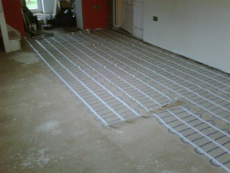
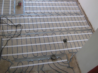
The heating mats come rolled up with the electric heating element already taped to a mesh to ensure that when laid out, the element is equally distributed on the floor.

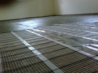

Once taped to the floor you put a layer of adhesive over the top (unless you’re brave enough to lay the tiles directly on top), let that dry then lay the floor tiles as usual. The installation instructions indicate that you should do a resistance check at all stages of the installation. They didn’t say what you should do if the resistance goes up massively (due to damage or fracture of the wire) after the tiles are down. The inference was I think to run screaming outside with your hands flailing above your head prior to phoning professional installers to rip out your attempt and to do the job for you properly.
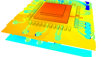
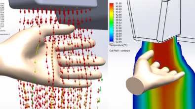
Thermal simulation of such an application lies somewhere between what FloTHERM and FloVENT was designed to do. The former having the ability to simulate Joule heating, including the temperature dependent effects of the electrical resistivity of the wire. The latter having the ability to predict specific aspects of the resulting human comfort such a comfort temperature, PMV, PPD etc. Let’s just say I used FloTHENT.
 From a qualitative perspective you can clearly see the effects of the hot wires and how the heat diffuses down into the concrete screed. But hey, qualitative, shmalitative, who’s interested in pretty pictures? For an accurate simulation it’s critical to ensure the correct boundary conditions are defined for the heating element itself. More on that next time.
11th August 2011, Ross-on-Wye.