The art of modelling using CFD. Part IV – Fans
Sometimes the ability to apply artistic interpretation of your virtual product to your simulation model of it is limited or dictated (take your pick) by the available capabilities of that simulation tool. CFD simulation is quite a young technology, application to electronics cooling newer still, a mere 21 years old. Always pushing the limit of available computing resource, always adapting to the ever increasing need for accurate AND fast predictions, such tools continue to adapt. Couple this to the prevalence, and relative complexity, of fans in electronics cooling and you’ll be faced with a few options regarding their representation.
The use of the term ‘compact model’ is used extensively in the electronics cooling simulation field. ‘Compact model’, a tautology if ever there was one! All models are compact to some degree, they are never ‘more’ than the reality they represent, just reflections of it. For fans you have two options (well, in some tools) either represent the blades and their rotation explicitly, a detailed representation so to say, or use a compact representation of the fan. A compact representation will have the following characteristics:
- Have the same key behaviours as the real object
- Be computationally efficient
- Require a small amount of data to characterise it
A fan spec sheet nearly always contains characteristic information that can be used to define a compact model; the fan curve, a graph that relates the pressure drop over the fan vs. the flow rate of air that fan can push through itself under those pressure conditions. Beyond that you’ll just want to know the outer (cowling) diameter, the hub diameter and thickness. O, and the rmp it rotates at, that info can be used by the simulation software to determine how much the air swirls round as it comes out of the fan. Nice and simple.
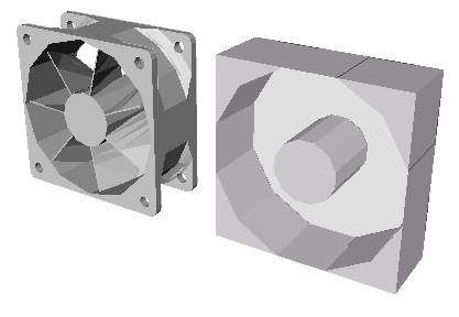
OK, what are the pros and cons of either method? Well, a fan curve is not totally BCI (boundary condition independent). It will be valid for the test environment it was measured in, less valid when say the fan is placed real close to a plate. Some manufacturers provide some indication of exactly how the fan curve is degraded under such circumstances, most don’t. A detailed model of a fan, with the blades defined in all their glorious 3Dness will not suffer such fan curve issues. However it does strike me that it must be awfully difficult to get hold of a 3D cad model of the blades, they’re like snowflakes, unique and real difficult to get hold of, they certainly aren’t available with the spec sheet. I also doubt the fan manufacturer would want to provide such 3D cad data, you’re more than likely go off and manufacture it 😉
You really don’t want to be putting a fan so close to something as to invalidate its fan curve. Compact fan models are nearly always good enough. Beware of CFD tools that lead with the ability to model fans in detail, it’s quite possible they do so because it looks better, it looks more accurate, rather than providing better value in terms of accuracy and overall time required to use.
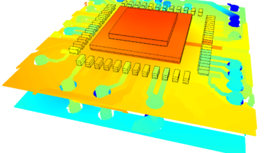
If you don’t believe me just stare at the image below intently for a couple of minutes. Yes, you are feeling drowsy, sleeeeepyyy….
20th May 2010, Ross-on-Wye