The art of modelling using CFD. Part III – TIGs
Never trust a TLA (three-letter acronym) or those who use them, unless the abbreviation provides some value in terms of repetitive usage or is accepted as an industry standard. Too often TLAs are used as a screen between those who are listening and the incompetence of the person talking. TIGs (thermally insignificant geometries) as a TLA is neither useful nor accepted, I just made it up. Thermally insignificant geometries however are at the heart of the art of CFD based electronics cooling modelling.
Today, the MCAD design environment can be considered the backbone of the mechanical design process. Repeatable use of perspective pioneered in Rennaisance art is said to have enabled the industrial revolution of the 18th century. If you can’t draw it effectively, you can’t make it efficiently. MCAD software today is used primarily as a method of capturing design intent for subsequent manufacture. Less of an art form than a science. The geometric information required to enable manufacture, production quality 3D descriptions, nearly always have too much information necessary for an air-flow/thermal simulation. (Though often not enough information for an EMI/EMC simulation but that’s another story…).
You would think that having too much information is a good thing. Yeh, and my children would think that living in a sweet shop is a good idea. The art of modelling is creating a realistic yet computationally efficient representation. You could include geometric features that play an insignificant part in the resulting thermal or air flow behaviour but the only affect would be to increase the time required for a simulation to be performed, maybe from hours to days.
When is something ‘insignificant’? That all depends on its context. The decision of when to ignore a geometric part or feature from the simulation model requires a certain amount of intuition and experience. This is one of the reasons why it is recommended that a user of a CFD software has at least some basic fluid dynamics understanding. If in doubt do some comparative modelling, create a model with a feature included then not included. If the results do not change then you’re good to go on ignoring that feature from this point on. I’d like to provide a cook-book on making such decisions but I don’t think the advice can be reduced that easily (certainly not in the scope of a blog).
Back in the day when a big CFD model had 100,000 cells and took 12 hours to run users were forced into making such simplification (rather geometry ‘preparation for analysis’) judgements regularly. Today, with both the availability of highly detailed MCAD 3D data and more advanced computation hardware, such decisions, for right or wrong, are being ignored more and more. The result is less experience required from the user, but much longer solution times compared to what could in theory be achieved. Is this good or bad? I’ll reserve judgment as different organisations have different strategic objectives in this regard.
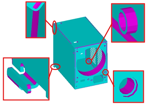
Suffice to say that with a little bit of experience the above PSU housing can be simplified down to the following with solution times reducing by an order of magnitude without results of interest being affected in the slightest.
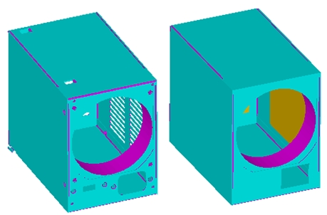
Note the grille representation using a ‘resistance’ object as described in the previous blog. Such simplifications can be made at the touch of a button using FloTHERM’s ‘FloMCAD Bridge’ application window. Software designed to truly meet the industrial time scale needs of the thermal designer!
17th May 2010, Ross-on-Wye