The Most Extreme CFD Model Ever Ever – Explained
The ability of FloTHERM to resolve a massive disparity in geometric length scale in a single model is for me its greatest strength. By not having to make simplifying assumptions to ignore either extremely small or truncate extremely large geometric parts and features, simulation accuracy can be better assured. The ‘die in a city’ model in the previous blog resolved a length scale of 1,000,000,000:1. Admittedly not a common type of model (unless you are a deviant simulation masochist) but it does prove a point. But just how does FloTHERM do it…?The specification of geometry in a 3D simulation model is relatively straight forward. It’s just a case of creating objects of the appropriate sizes and locations and assigning the correct physical properties such as material, surface finish etc.
A building is simply a block of dimensions 40mx40mx150m. A PLCC is a collection of block type objects, e.g. the objects representing the bond wires having a smallest length dimension of about 30 microns. Just a question of putting the right numbers in.
When conducting a CFD type simulation (in fact all 3D simulation approaches that use a Eulerian type approach) you have to subdivide the 3D space into a series of tessellated little volumes (cells). When a ‘solution’ is conducted by the code, values for temperature, pressure, speed etc. are calculated in each of these little cells. You’d want big cells for regions where speed, temperature etc. do not change much such as in the atmosphere and really insy wincy small cells for when there is a rapid change in these values in a small space such as inside an IC package. So, large cells to resolve the big stuff, small cells to resolve the very small AND a need to ensure that all the cells are tessellated as well.
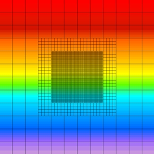
The approach FloTHERM uses is what we have coined a ‘localized grid’ method. It can be viewed as a subset of the chimera overset grid method but with lots of tweaks and specialisations that have taken us years to evolve and refine. It allows for a non-conformal interface accommodating an N:1 refinement ratio of cells between two spaces of the volume. This allows the cell size to reduce at the interface whilst still ensuring tessellation is maintained. Here’s an example of a 1D heat configuration (top to bottom heat flow) model solved as a 2D conduction model with two nested localized grid spaces inside the top level grid:
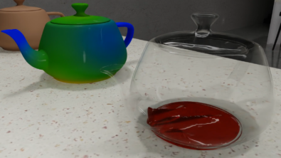
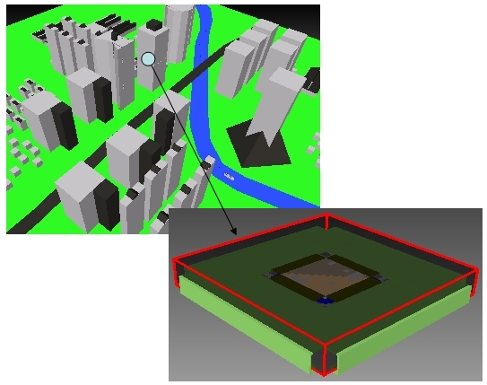
For the ‘die in a city’ example 6 nested grid spaces were defined, successively refining the mesh to resolve all the buildings -> the building in question -> the floor level -> the room -> the modem unit -> the PLCC+Heatsink (top half of building and heatsink wireframed for clarity):
Whilst other CFD codes (with what they purport to be more ‘advanced’ gridding schemes) would struggle with such an example, the productivity work horse that is FloTHERM munches it up!
12th January 2010, Ross-on-Wye