How-to: Invert your thermal model to good effect
Thought I’d follow the previous post on this subject up with a slightly more detailed description of exactly how to set-up a model with a fixed temp die and observe the resulting simulated power dissipation. “Hey Robin, this should really be done as a AppNote on SupportNet”. Can’t argue with that but posting it here as well will give everyone a glimpse of the actual operation of FloTHERM and FloTHERM.PCB.
So, in FloTHERM.PCB it’s very easy. Where you normally define the power dissipation type a “?” instead. This will set the junction temperature in the die equal to the defined Maximum Junction Temperature:

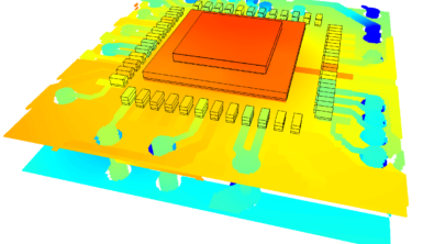
And after the thermal solution you get:
 In FloTHERM it’s a case of changing your thermal or source attribute from a total source of temperature (i.e. power) to a fixed value (i.e. temperature):

After a thermal solution use of the absolutely-superb-if-I-do-say-so-myself (asiidssm for short) new V8 feature; Tables ‘Solid Conductor Summary’ tab where you can read off the net power coming from the Die object (as opposed to summing the net fluxes from the individual 6 sides like you used to have to do):

The only final thing to be aware of is that when you fix power and derive temperature the former is constant across the die whilst the latter is allowed to vary. Same is true the other way round, if you fixed temperature and derive the power the power dissipation variation may not be constant (though with k of silicon ~130 W/mK it’s not going to be far off).
24 July 2009 Ross-on-Wye