Relating AM Conditions and Fatigue Performance of 3D Printed Metallic Parts
You must have heard about Additive Manufacturing (AM) and if you haven’t it is currently a disruptive change in the manufacturing process industry. Widely known as 3D-printing, Additive Manufacturing refers to a family of production processes which enable the production of complex parts layer by layer. The AM process allows one to produce almost any shape by creating parts using only the material that is needed, as opposed to subtractive manufacturing, which involves cutting away what is not needed from larger material volumes. AM can be based on metals and polymers using a variety of processes. In this blogpost, we focus on metal alloys.

Benefits of Additive Manufacturing
Additive manufacturing offers many benefits to product design engineers:
- Diversity of complex lightweight structures designed and manufactured with great design freedom
- Less waste as compared to traditional subtractive manufacturing
- Little lead time after designing a 3D model (can “directly” be 3D-printed)
- Natural link with topology optimization (typically leads to complex structures that cannot be manufactured with traditional methods).
One key design freedom in AM is the use of lattice structures, periodic lightweight structures that can be chosen from a design library and printed with AM. Using a novel approach [1], the topology optimizer can be used to decide where to put bulk material, where to put lattice structure material, and where to put no material (void). This allows one to virtually design the AM structures and benefit from the lattice structure material properties. These will provide structural support in addition to their thermal and air/fluid conductivity properties.
Challenges of Additive Manufacturing
But there are also challenges. One of them is the lack of predictive CAE tools with enough predictive quality to capture the effects of the different complex phenomena occurring during the AM process. This means that the industry must rely on expensive tests for which the results only become available very late in the product development process. Siemens PLM Software is working on providing efficient solutions across different attributes (strength, stiffness, NVH, fatigue life …), aiming to bring in place a predictive CAE toolchain for AM. Furthermore, due to the complex nature of the metal AM processes, the 3D printed components will have locally varying surface roughness, porosity content, and microstructure. These specific aspects can be related to process settings, but also build orientation and post treatment (surface finishing, heat treatment etc.). Consequently, available material property databases for conventionally produced metals cannot be used directly. As a result, considerable amount of dedicated testing of AM samples is recommended to get insight on the most important effects of AM process conditions on the AM product performance.
How AM effects Fatigue Performance
Fatigue performance strongly depends on the AM process conditions. This is illustrated in Figure 1: for a single material (Ti6Al4V) produced with Selective Laser Melting (SLM). Applied stress reports a wide range as a function of the cycles to failure due to variations in sample quality, porosity content, process conditions, and test procedures. Thus, one cannot draw firm conclusions about the fatigue life of the material.

Figure 1: Literature fatigue data for SLM Ti6Al4V (courtesy of KU Leuven, as presented in [2][3])
Within this challenging scope of fatigue life prediction of AM products, Siemens PLM Software participates in a Strategic Initiatives Materials in Flanders (SIM) R&D project called “FATAM” (“Fatigue of Additive Manufactured components – Relating AM process conditions to long-term dynamic performance of metallic AM parts”, 2017-2020). Next to the SLM technique, the FATAM project also deals with Electron Beam Melting (EBM) and Direct Energy Deposition (DED) techniques. Figure 2 gives an overview of different samples produced with these techniques by several consortium partners.

Figure 2: Overview of AM samples produced with different techniques by different FATAM partners
The aim of the FATAM project is twofold:
1. Establish a material specific database of Ti6Al4V (titanium alloy) and 316L (steel) S-N curves for different AM process conditions. The layer by layer production leads to orthotropic material strength properties, such that tests must be performed for different build orientations. Also, the effects of thermal and surface treatment are systematically evaluated in an experimental context.
2. Establish numerical methods and tools to design and improve the design of AM structural components for fatigue life – including accurate multi-scale prediction of the local effect of fatigue-critical factors (e.g. build orientation, surface roughness, porosity…). This reduces the required testing efforts significantly, as well as, using newly developed and validated S-N curve based methods including smart extrapolation methods for S-N curves.

Figure 3: FATAM Project Overview: Accurate fatigue life estimation of an AM component.
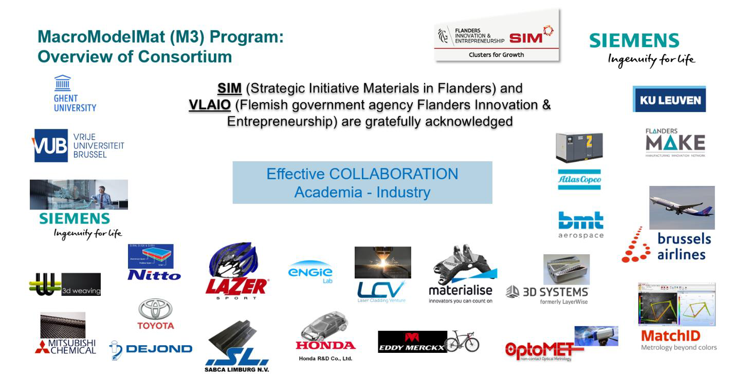
The FATAM project is part of the SIM MacroModelMat (M3) program, which addresses the gap in efficient macro-level predictive modeling tools for new lightweight material systems. The key objective is the development of an integrated numerical simulation methodology for the multi-attribute mechanical behavior of new lightweight materials such as fiber-reinforced composites and 3D printed materials. The M3 program covers predictive CAE modeling for multiple functional performance attributes such as static strength and stiffness, dynamic strength (fatigue), crash worthiness & crush and NVH/Acoustics. In the M3 program, Siemens PLM Software as coordinator and solutions/software provider has the main translator role, leveraging and further developing the state of the art with the participating universities (KU Leuven, UGent, VUB) and knowledge center (FlandersMake) to meet the materials modelling and design engineering challenges of the industrial end user partners.
See full consortium overview in Figure 4, and more information at http://www.sim-flanders.be/research-program/m3).

Figure 4: The MacroModelMat (M3) consortium.
Acknowledgement:
Siemens PLM Software gratefully acknowledges SIM (Strategic Initiative Materials in Flanders) and VLAIO (Flemish government agency Flanders Innovation & Entrepreneurship) for their support of the IBO project FATAM, which is part of the research program MacroModelMat (M3).
Reference:
[1] Hunor Erdelyi, Alain Remouchamps, Stijn Donders, Laszlo Farkas, Christophe Liefooghe, Tom Craeghs, Wim Van Paepegem, “Lattice structure design for additive manufacturing based on topology optimization“, Proceedings of NAFEMS Seminar “Simulation Driven Engineering”, Neuendettelsau, Germany, Nov. 20-21, 2017.
[2] Brecht Van Hooreweder et al., “Exploratory work on fatigue of SLM-Ti6Al4V“, KU Leuven internal report, 2016.
[3] Hunor Erdelyi, Nicolas Lammens, Wim Van Paepegem, Brecht Van Hooreweder, “Impact of Additive Manufacturing Process Conditions on the Fatigue Performance of Metallic Components“, NAFEMS DACH Conference 2018, 14 – 16 May 2018, Bamberg, Germany.