Circuit breakers, thunders and the challenges of multiphysics

I suspect nobody of us is eager to be hit by a lightning strike. The experience would be – in the best case – very painful. Lightning is a violent electrical discharge that turns the gas into a hot, electrically conducting channel. Through this channel, an electric current suddenly releases energy in form of sound waves, visible and ultraviolet radiation, heat. The hot gas is in a state of matter known as “plasma” and the discharge path is often referred to as “plasma arc”. Now, we don’t need a thunderstorm to ignite a plasma arc. In electric circuit interrupters known as “circuit breakers”, a plasma arc burns whenever one opens the circuit while the electric current is still flowing.
The job of the circuit breaker is – suprise surprise! – to break the circuit, namely to safely quench the arc by stopping the flow of electricity.
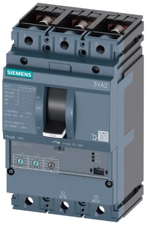
A low voltage circuit breaker manufactured by Siemens AG. 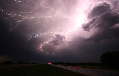
Lightning is a violent electrical discharge that turns the gas into a hot, electrically conducting channel through which an electric current releases energy in form of sound waves, radiation, heat.
The development of new circuit breakers is challenging due to the complex physics and the difficulty of dealing with lightning discharges in the lab. A new prototype of low voltage circuit breakers could easily blow up in your lab if the arc builds up too much pressure. Here’s why numerical simulations can come into play as a valuable tool. Of course, turning to the digital version of a circuit breaker is not pain-free. Simulations are rather complex. One has to account for fluid dynamics, radiation, electromagnetics, ferromagnetism, turbulence, heat transfer, geometry motion, numerics, you name it. However, at least the only things that can explode in your laptop are the equation solver residuals.
Safety first
In this post we are not speaking about fancy plasma lamps but rather safety switches! They have to be robust with minimal maintenance. And reliable even if you don’t use them for long time. They should be able to survive under sudden stress (short-circuits). Moreover, they are not supposed to be disposable one-time devices but they have to be able to undergo many switching operations. So a proper design shouldn’t only account for reliability and safety but also lifetime.
And you do want to rely on your parachute even if it has been already used, don’t you?
Why is it so hard to deal with circuit breakers?
Circuit breaker manufacturers usually face the nontrivial problem of not being able to carry out meaningful measurements in the arc chamber because – during contact opening – the flow environment is too harsh. Indeed, the flow can be as hot as 20,000 K or 30,000 K (the surface of the Sun is less then 6,000 K). Moreover the peak of the arc electric current in short-circuit conditions can be high. Last but not least, the chambers where the arc burns are quite small (few cm) and the action is fast (in AC at 50 Hz, typical timescales of the arc are about tens of ms).
So you guys understand that people cannot place sensors where the real action is, sensors that should satisfy all the above-mentioned requirements. And by the way survive erosion/ablation caused by electric current, radiation and high temperatures [1].

Limiting the shooting-in-the-dark approach
According to the research engineer who kindly provided the geometry of this low voltage circuit breaker, designing a test for a new product needs at least one month. Well, “if everything goes smoothly”. In fact, you might have to come up with a new design, manufacture a number of prototypes and test them in the lab under different conditions. Even worse, new designs tend to be still based on the good (?) old trial-and-error approach. Needless to say, simulations have the advantage of allowing a more controlled and educated investigation of circuit breakers’ design.
A realistic simulation
Simcenter STAR-CCM+ allows the use of a broad spectrum of physical models that – and I cannot emphasize this enough – can run simultaneously in the same simulation instance. In other words there is no need of co-simulating with another software. In fact, people often have to use third-party tools in order to automate the interface between various different software tools.
We ran the simulation below on 16 processors. It took one week without optimizing the setup. The computed voltage difference is very close to the measured one. The animation shows the evolution of the temperature of the arc during contact opening [2]. The arc temperature in fact correlates with the electrical conductivity distribution and hence the electric current. A known manufacturer has provided us with the geometry, which corresponds to a real product.

For the ones of you who are familiar with the topic, the simulation includes the following features:
- Ferromagnetism: Nonlinearity of the magnetic permeability of the splitter plates
- An iterative Finite Element Magnetic Vector Potential solver for the electromagnetic equations (based on vectorial elements)
- Evolution of eroded metal vapor, impacting electric conductivity and radiative emission/cooling
- Arc-root voltage drop and surface Ohmic heating at the metal-plasma interface
- Electrode motion (prescribed), mesh morphing and the occasional remeshing
- No need of cosimulation. Simcenter STAR-CCM+ invokes both the Finite Volume and Finite Element solvers in the same simulation instance
Enjoy the video!
Our external partners could even recognize from the animation the points that are melting and where erosion takes place during their lab tests. In fact, studying the points that have suffered the highest thermal stress tells you about the weaknesses of your design. So you get some insight into possible reasons for a failed current interruption. The animation shed also some light on the interaction between the arc and the spatial orientation of the splitter plates.
[1] There are in fact indirect measurement techniques. They are frequently carried out in simple/mock-up geometries in the lab, where one usually analyzes the spectrum of the radiation emitted by the arc – integrated along the line of sight. From that, one can partially reconstruct the profiles of temperature, pressure and plasma composition, provided some assumption about the shape of the arc can be made.
[2] This simulation has been carried out as a joint effort between Siemens PLM and the Hochschule fuer Technik Rapperswil (Switzerland). We thank in particular the help of Roman Fuchs.
Learn more about plasma simulation using multi-physics software to model plasma processes in semiconductor fabrication in this webinar.


