Multiscale simulation in the process industry – better together
Do one thing and do it well.
Doug McIlroy, Bell Labs
This is one of the key elements of the Unix philosophy, which made Unix and its variants so powerful. It means not only that a program should be small and focusing on one aspect and solve it efficiently, it also inherently includes another expectation: The output of one program becomes the input of another, so the programs have to communicate with each other. Following these simple design rules, large systems can be and have been created efficiently.
Do one thing and do it well – the engineer’s way
As a philosophy, this is not only relevant in the Unix world. You can actually translate it into our daily engineering practice. Think about a complex problem like developing and building a new process for a chemical product. On the one hand we need engineers with expert knowledge in a specific area. On the other hand this knowledge is of less use, unless you can share or communicated it to others. So it is vital to have and communicate expert knowledge to get the most out of it.
The silo-dilemma in the process industry
As process industry engineers we perform simulations on a range of different scales and purposes.
We use flow-sheet simulations for designing and validating the full process from raw material to the final product in terms of heat and mass balances, sizing and cost.
We conduct process simulations to get a deeper understanding of the underlying chemical, physical or biological processes in unit operations, a basic step in a process. Such simulations typically simplify the problem at hand with assumptions regarding the flow. They assume other properties like ideal mixing in stirred tanks or plug-flow in tube-like devices. Their focus is on the accurate description of the detailed physics.
Finally, CFD simulations allow the detailed analysis of flow, turbulence and other relevant parameters in the equipment.
However, those disciplines are barely interconnected in a smart way.
Process Industry – a challenge for conventional CFD
The most straight forward idea would therefore be an integration of one into the other: Since most processes depend on local conditions, there is an obvious benefit to integrating process models into CFD. In practice, however, the following reasons limit the applicability of this approach:
- Depending on the system, solving the related additional equations can generate a considerable overhead and lead to long computing times.
- The chemical-physical processes often happen on different time scales to the flow and mixing time scale. E.g. in fermentation processes in lab scale, the mixing is typically fast in the order of seconds but the fermentation reaction is slow. This requires simulated times in the order of hours or days, which leads to unacceptable computation times in time-dependent simulations.
- For design studies or variation calculations during operation, you need to achieve results in a short time, usually in seconds or in a few minutes. Typically a CFD simulation including the detailed process physics will not cater for such a runtime requirement.
Today, therefore, many still do process modeling in extremely simplified geometries assuming ideal conditions.
Divide and Conquer – Realizing Multiscale simulation in the process industry
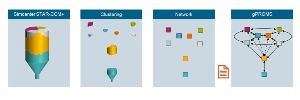
An alternative way to integrate non-ideal mixing or, more generally, non-idealities within processing equipment is by means of a compartment or multi-zonal model. This approach divides the equipment volume into a network of interconnected zones, see figure 1. The assumption is that each zone behaves like an ideal reactor. Each can can exchange mass flow and, if required, other variables with its neighbors. The value of these variables can be extracted by averaging results from a detailed Simcenter STAR-CCM+ simulation. One can then use those in a process modeling environment like gPROMS by PSE, a Siemens Business. Consider it as kind of a very coarse CFD simulation, but improving the results significantly by considering locally varying conditions. In fact, several groups used this multiscale simulation in the process industry to simulate, amongst others, crystallization, polymerization and bio reactors. [1-3]
Goodbye, macro
In the past I used this approach based on some additional coding and programming. I wrote macros to split the geometry. I generated reports and nested derived parts to extract all relevant information. Obviously, I needed to do a lot of annoying testing, debugging and validation. It was doable. But -to be honest – it was an error-prone approach, took a lot of time and required adjustments to the macros in many cases. It was a waste of valuable engineering time, to focus on the actual engineering problem at hand.
Today, I no longer need my macros because the full process is implemented in Simcenter STAR-CCM+. This makes the coupling much easier and quicker. I just take my converged simulation, specify the decomposition and select the variables to be exported, step the solver. And, I am done.
Simcenter STAR-CCM+ writes all data into a single file which one can import directly into gPROMS. On top of all that, not only can Eulerian field variables be exported but also Lagrangian data, which is a key requirement for spray dryers or other applications where discrete particles are of importance.S
This workflow makes multiscale simulation in the process industry as easy as never before.
An example of multiscale simulation in the process industry at work
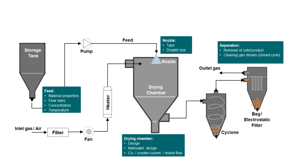
Imagine a spray drying process as shown in figure 2 where hot gas dries a slurry, as used for producing milk powder, detergent, fertilizer and many more products. The heart of the process is the drying chamber where the hot gas gets in contact with the slurry. The usage of small droplets provide a larger surface area, thereby speeding up the drying process. The initial size and distribution of the droplets depends on the number and type of the injection nozzle(s), as well as physical properties like viscosity of the slurry or feed stream. The droplet sizes also change in the chamber due to both the drying process and coalescence and break-up events caused by the local flow and turbulence conditions.
System complexity
Before it enters the drying chamber the drying gas is cleaned and heated. This means that for designing and optimizing the size and shape of a drying chamber process engineers need to consider a bunch of aspects: the arrangement of the inlet streams, the drying rate and residence time and any constraints affecting the product quality, such as the maximum allowable temperature of the droplets. Of course, downstream processes like product separation in cyclones, removal of fines in filters and cleaning or regenerating the outlet gas are all affected by the design of the drying chamber.
Physics complexity
Another important aspect of the drying chamber simulation is the drying of the droplets themselves. This typically happens in two stages with different drying rates. In the first stage diffusive mass and heat transfer limit the rate, while in the second stage a solid shell or crust at the outside can form which acts as an additional mass transfer resistance and hinders the drying. Additionally, the varying droplet size distribution due to coalescence, breakup and agglomeration needs to be taken into account. In some spray dryers, fouling can also be an issue, either at the nozzle(s), at the outlet or on the chamber walls.
How can we solve these challenges?
From a CFD standpoint we can easily setup and run a drying chamber simulation if we know all relevant boundary conditions, have a suitable model for drying as well as a suitable population balance model. The remaining challenge is the computational cost, especially in plant scale when the number of droplets is huge. Things become even more challenging when you want to analyze variants or when the startup phase of the process is of interest.
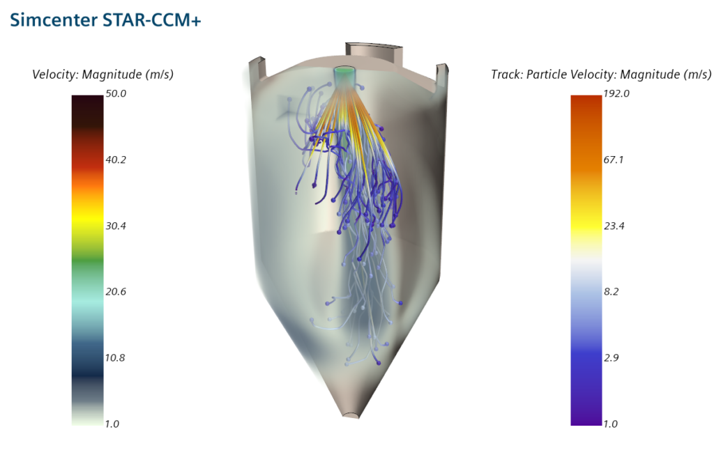
From a process modeling point of view where each unit (operation) is represented by a set of equations the runtime is typically not an issue. This holds even for dynamic processes. In the simulation it can be augmented easily by improved models. On the other hand, these 0D or 1D models neglect any spatial in-homogeneities. The shortcomings of this approach can be easily demonstrated by looking into the results of a detailed spray dryer simulation: Mass and heat transfer is a function of the relative velocity, available surface area and temperature difference between the droplets and the background fluid and these parameters vary locally in the drying chamber as depicted in figure 3.
The best of both worlds
By combining both methods, I am able to overcome these shortcomings. I start with a converged CFD simulation of the flow in the drying chamber as shown in figure 4 on the left.
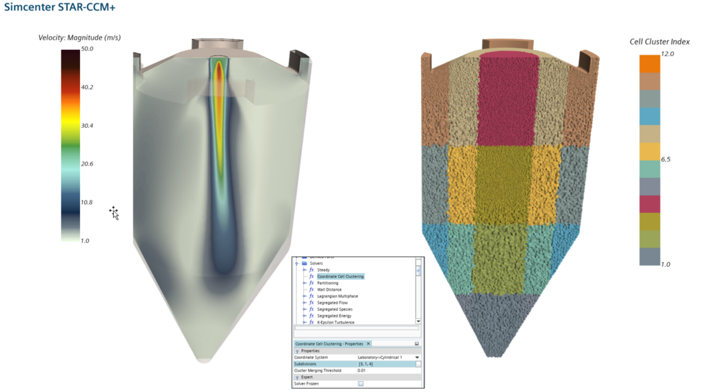
Divide…
The first step is to split the geometry in such a way that the relevant variables do not vary too much in each zone. One can do this by specifying the number of zones in each coordinate direction and then stepping the Coordinate Cell Clustering solver. If the zoning is not satisfactory, I can simply change the parameters and step the solver once again.
If I am satisfied with the clustering I just select which fields and which boundaries I want to export into the output file. In this case, it is just the mass flow of the gas phase between the zones and the normalized droplet mass flow. The droplet mass flow is exported as a droplet size-dependent distribution.
…and conquer
I then can import the file into my existing process simulation project in gPROMS. The import automatically detects the number of zones and their connectivity.
Finally, I am ready to run my process simulation in gPROMS. In this case, it is a transient simulation over 6 minutes of simulated time. Oh, and the runtime is in the order of a few seconds on a single CPU!
Multiscale simulation in the process industry – the best of both worlds
So, to summarize the benefits of the hybrid multizonal modeling and to link it back to the Unix philosophy: We have two expert tools, Simcenter STAR-CCM+ and gPROMS. Each of them does an excellent job in its area, but now in the upcoming Simcenter STAR-CCM+ 2020.3 release, they can talk to each other via hdf5-files – allowing he best of both worlds to be combined. You can now simulate large scale processes with increased accuracy in terms of geometrical details, flow and process modeling and speed. And this opens the door to improve and optimize many different processes in plant scale. This makes multiscale simulation in the process industry accessible to the masses. You don’t believe it? Then stay tuned, for prove on this in my next blog and the upcoming release of Simcenter STAR-CCM+ 2020.3.


