Machine Frame Digital Simulation: Crafting an Efficient FEA Workflow (Part 1)
Editor’s note: This article is the first in a series of articles written by David Haag of Haag Enterprises, an advanced digital engineering shop specialized in delivering product development and industrial equipment and automation services. If you like this article, come back to the Simcenter Blog in July for the next article in the series.
ASI, Automated Systems International, is a team of creative engineers based in Prospect, KY that specializes in the design, build, and installation of industrial equipment. Most of their projects are custom machines, meaning they start with a blank canvas and have one shot at getting it right, unlike OEM companies that can leverage proven designs that evolve into next-generation products. For one-off projects, any mistake on critical components can erode profit margins, delay installation, and ruin reputations, which is why ASI leverages my digital simulation services in the early design phase.
“David, this is Kent from ASI. I have a FEA project for you. We are designing a new machine and I need to know two things: (1) is the frame is strong enough/did we over design it and (2) can you remove any cost (components, weld fixtures, fabrication time, etc). If this machine is a success, our client is talking about ordering 2 or 3 more of them.”
The conversation was longer than that, because we engineering nerds get jazzed up about machine design and can talk for days. The following is an overview of my workflow for creating accurate and efficient finite element models using Solid Edge and Simcenter Femap.
Step 1: CAD Data and Change Management
We start by importing a .stp file into Solid Edge and discover that it contains the entire machine (bolts and all), which I prefer, since it allows me to choose what I want to export for the FEA study. This Solid Edge assembly will contain the customers original design, plus any changes I want to make for what-if scenarios to run in Simcenter Femap. I select the frame weldments and force producing components (actuators, motors, etc.), show only, and export as a Parasolid using the Export Display Only option. Now, you might be wondering why not just by-pass Solid Edge and import the .stp file directly into Simcenter Femap? That’s a great question and the answer is you can; however, by leveraging built-in data management tools and synchronous technology in Solid Edge, I can perform quick design changes and export only those changes into Simcenter Femap.
Step 2: Building an efficient FEM (Finite Element Model)
In my experience, there are two common types of FEA people: (1) those who use solid elements for everything, and (2) those who use a hybrid element approach. For the solid elements for everything person, sure it’s faster to setup (material, tet mesh, glue connections, solve) and looks more like the CAD model, but the solve time can increase by an order and magnitude, depending on the model size, and glue connections across the board won’t simulate real-world load transfers and contact. When using the hybrid approach, you’ll have more upfront modeling time, but the ROI is achieved due to the fast solve times.
Mid-Surfaces and Plate Elements
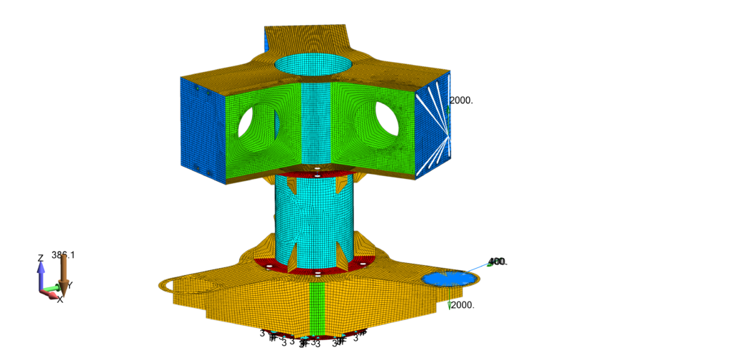
Let’s jump into Simcenter Femap and import the Parasolid that we exported from Solid Edge. Since this frame is a classic thin-walled structure, I create mid-surface geometry for each body solid, clean up gaps at T-junctions by extending to common intersections, and apply meshing attributes. Next, I create respective Groups for the top, center, and bottom weldment. The Group functionality in Simcenter Femap is powerful and used for organizing complex models, based on geometry and/or FEM entities. Essentially, it allows the user to swap between different regions of the model during the FEA process, as we’ll see in Part 2 when we analyze results in post-processing. Since we have applied meshing attributes to the geometry, we can choose surface mesh and the option to only mesh objects with properties. This prevents us from meshing any construction geometry by mistake.
Modeling the Bolted Connections
For the bolted regions, a pad/washer can be created using commands in the Meshing Toolbox. Edits made using meshing toolbox commands will update the mesh in real-time or you can choose to delay the real-time updates until all selections have been made (the best option for larger models). Out of the box, Simcenter Femap includes some nice APIs that accelerate modeling tasks and one example is the Hole-to-Hole fastener. The only user inputs are choosing the curves of the top and bottom hole, then Femap creates a 1D bar element at the correct diameter (based on curves selected) and connects to bolt to the curves via rigid spider elements.
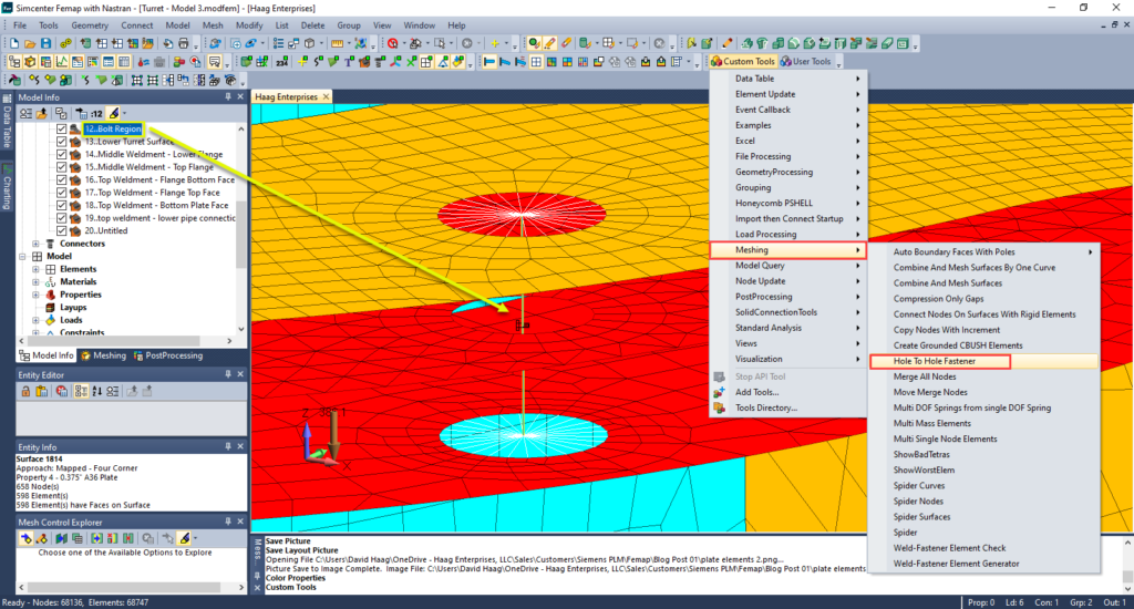
Out of the box, Simcenter Femap includes some nice APIs that accelerate modeling tasks and one example is the Hole-to-Hole fastener. The only user inputs are choosing the curves of the top and bottom hole, then Femap creates a 1D bar element at the correct diameter (based on curves selected) and connects to bolt to the curves via rigid spider elements.
Boundary Conditions
The only fixed constraint in the model is the base flange, which is bolted to an indexing table (not part of the FEM), so each curve will have a fixed constraint applied. Loading of the structure is a result of the actuators and gravity. The location of the actuator load is offset from the mounting face, so we can locate using the construction geometry and transfer to the mounting faces using rigid spider connections. An equal and opposite force will be applied to the lower structure in the same fashion.
Step 3: Incrementing Model Complexity
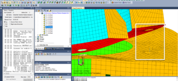
Ideally, we want a model that solves fast and yields accurate results; however, solutions involving geometric non-linearities and contact can have long solve durations. The last thing you want to happen is for a solution to run for a while, only to find a silly mistake was made that voids the results. As a quick model check, I will run a Modal Analysis, even if I’m not interested in the mode shapes, because it solves fast and reveals if connections are not functioning properly. For instance, if a bolted connection is missed, the parts will “fly apart” in the Modal solution results, making it easy to identify, as shown in Figure 4.
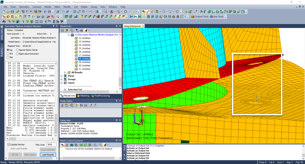
After updating the glued connection distance check, we re-solve, and if no errors exist, we can be confident that our connections are now functioning as intended.
Linear Static – No Contact or Bolted Regions
For this solution, we’ll disable the bolt regions and simply glue the flanges together at each bolted interface. This approach bypasses the detailed interaction of contact between the flange interfaces, but still transfers the loads across the interface. The low level stresses and deflection values tell us that our structure is strong enough, but is it over built. The advantage of modeling with plate elements becomes apparent now because plate thickness can change in a matter of seconds and quickly resolve. By reducing the material thickness, the deflections have consequently increased, which was expected, but how real are they? A linear static analysis doesn’t take into account membrane stresses because the stiffness matrix is established once and not updated during the solve. The next step would be to use a Nonlinear Static solution.
Nonlinear Static – No Contact or Bolted Regions
In the Simcenter Femap solution manager, we can copy our Linear Static solution, select Nonlinear Static solution, set # of load steps, verify boundary conditions copied over, rename, and solve. The deflections are identical, which tells us that membrane stiffness had no contribution to the structure’s stiffness, so we’ll perform our next analysis as Linear Static with contact and bolted regions.
Linear Static – With Contact and Bolted Regions
We disabled the bolted regions in the first linear static analysis, so they must be re-enabled. To understand if the bolts are large enough, we apply a bolt preload to each bolted region. To resist the bolted preload, we must add contact regions between the flange interfaces, which can be done using Automatic Connection Regions. It’s always wise to validate using the filter highlighter and selecting displaying directions arrows to ensure the correct plate element side is being used. If these are incorrect, the plate will have excessive travel before Nastran detects contact, resulting in false deflection values.
Summary
By crafting an efficient FEA workflow, there’s more time for developing accurate digital models and optimization. As a result, late-stage design changes are non-existent, saving time and money, thanks to the powerful tools within Solid Edge and Simcenter Femap. And as mentioned at the beginning, if you liked this article please come back to the Simcenter Blog in July for the next article in the “Machine Frame Digital Simulation” series.


