Cementing the future of rotary kilns through simulation and intelligent design exploration
On a recent trail run along the foothills of the Santa Cruz Mountains near my home, I ran alongside the beautiful Lexington Reservoir. Curious to learn about why and when the reservoir was constructed, I got back home and looked up the information. As I read through the text, it got me thinking about other reservoirs and dams that I had visited, the Hoover Dam in particular. Did you know that the amount of cement that went into building the Hoover Dam is enough to pave a standard highway 16 feet wide, from San-Francisco to New York City [1]? While I continued with my online refresher on cement, I learned that there were three major developments in the manufacturing process that led to modern Portland cement [2]: the development of rotary kiln, addition of gypsum to control setting, and the use of ball mills to grind clinker and raw materials. With over a billion tonnes of cement being made per year [3], one could say that the rotary cement kilns are the heart of this production process.
The mention of rotary kilns quickly made me put my combustion hat on and sparked an interest in me to learn more about the latest efforts that have gone into addressing the design and performance of these systems from the standpoint of environment sustainability, operational efficiency, cost reduction, and innovation. Simply described, a rotary kiln is a long cylindrical drum that is installed horizontally, at a slight incline, and is slowly rotated about its axis. Raw materials that are to be processed are fed from one end and move along the length of the kiln as the drum rotates. The material gets heated by the hot gases created by the flames from the installed burners, and eventually exits through the other end of the drum before being cooled down.
 Figure. 1 A typical rotary kiln used in the cement Industry [courtesy KFS]
These systems are quite versatile and are not just used for the cement industry. They are used for processing raw materials and feedstocks via thermal processing or calcination in the lime, cement, metallurgical, pulp and paper industries, and are also used as incinerators for treating hazardous wastes. They can operate on a wide variety of fuels such as coal, biomass, heavy fuel oil, or natural gas and have burners specifically designed for multi-fuel use depending on the industry they cater to.
 Figure 2. (a) A multi-fuel (gas/solid/biomass) lime kiln burner, (b) multi-fuel (gas/liquid/petcoke) pulp and paper burner (c) light weight aggregate kiln burner (courtesy KFS)
Kilns are huge consumers of energy and are identified as a stationary source that emits more than 25 tons of nitrogen oxides (NOx) per year [4] due to the high flame temperatures encountered in these systems that create favorable conditions for the formation of NOx. The increasingly stringent requirements for emissions control across the globe are forcing equipment manufactures and companies operating them to develop new and cost effective ways of minimizing/controlling emissions. In terms of the NOx control strategies that are applicable to the lime or cement industry, one could either focus on the combustion process itself to lower NOx, or one could employ post combustion control approaches to reduce the NOx formed during the combustion process. Examples of combustion control approaches include using low NOx burners and low NOx pre-calciners, using staged combustion, through mid-kiln firing, or through process optimization, in which, the amount of fuel being fired or excess air being supplied is optimized to maximize thermal efficiency and system performance.
The most common post combustion control approaches, also known as secondary methods for controlling NOx, include Selective Non-Catalytic Reduction (SNCR), and Selective Catalytic Reduction (SCR). The SNCR process involves the injection of ammonia in the form of ammonia water or urea solution in the flue-gas, at a suitable temperature to convert NOx to N2. While the SCR process adds ammonia or urea in the presence of a catalyst to selectively reduce NOx emissions from the exhaust gases. Although SCR has been used extensively for gas turbines, internal combustion engines, and fossil fuel fired utility boilers, it has been less commonly used for cement kilns. One possible reason for the lack of widespread adoption of SCR for the cement kilns is due to the blockage of the catalyst under high dust environments.
The SNCR has been an attractive NOx control methodology for kilns as it requires lesser capital expenditure. However, the operational costs can become high for systems that are not operating optimally. An SNCR system’s performance in cement or lime kilns depends on the temperature (Figure 3), residence time, reagent injection rate, turbulence or the degree of mixing between the injected reagent and the combustion gases, oxygen content, and baseline NOx levels in the kiln. The effectiveness of the SNCR process is strongly dependent on the gas temperature. The process is relatively ineffective at temperatures below 800 oC and above 1150 oC. At temperatures below 800 oC, excessive amounts of ammonia are released to the atmosphere through the stack because of incomplete reagent dissociation, and at higher temperature, the reactions favor NOx formation and significantly higher reagent injection rates are required to meet the target NOx levels. The SNCR system is typically installed in the preheater of a lime kiln or the pre-calciner of a cement kilns as illustrated in Figure 4.
 Figure 3. Flue gas temperature range and effectiveness of SNCR (courtesy Haecheon Industrial Co)
 Figure 4. Schematic of rotary lime kiln and preheater
The use of Computational Fluid Dynamics (CFD) to study the design and performance of these systems is a cost effective alternative to expensive and time-consuming field tests. One recent case study of interest is that done by KFS [6] in which they carried out combustion and SNCR modeling of a rotary kiln with preheater in a lime plant using Simcenter STAR-CCM+. KFS has developed a methodology where they combine the combustion process optimization in the kiln along with SNCR optimization for cost effective, site specific NOx control. The methodology consists of three main steps:
Step 1: 3D simulation of the rotary kiln with models for turbulence, chemistry, and heat transfer for the gas phase, which is coupled to an in-house, developed and validated, bed chemistry model to represent the transport and heat transfer of solids in the kiln
 Figure 5. Illustration of gas phase and bed chemistry couplingStep 2: Mapping of the exhaust gas temperature, velocity, turbulence and species profiles to be used as the inlet conditions for the 3D simulation of the preheater. The raw material in the preheater is modeled as porous medium
Step 3. Modeling the SNCR process in the preheater by simulating the urea injection and the subsequent reactions to obtain information related to system performance such as mixing profiles, NOx reduction, NH3 slippage etc. The two-step urea decomposition via the thermolysis and hydrolysis pathways are modeled, and the subsequent NOx reduction based on the 7-step reduced kinetic mechanism is used in the simulations.
 Figure 6. Illustration of the three step methodology as adopted by KFSUseful insights about the effectiveness of mixing, the gas temperatures encountered in the preheater, and the resulting NOx reduction for a given urea injection rate at specified locations can be obtained from the 3D CFD simulations.
 Figure 7. Results from CFD simulations of the preheater geometry
In order to help improve the NOx reduction process effectiveness, a design exploration study was undertaken for the preheater geometry, wherein, a number of injector configurations were investigated. The injector positions and the total number of injectors were varied to identify an optimum configuration that could achieve the desired NOx reduction with minimum urea slippage. The best design resulted in approximately 60% NOx reduction of the baseline furnace value with a urea slippage of less than 1 ppm.
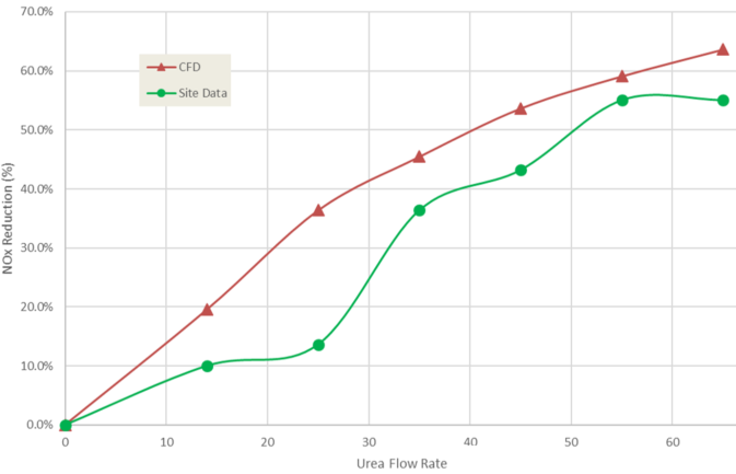
The effect of urea flow rate on NOx reduction efficiency for the optimum configuration can then be studied and compared to field data after the installation. In one example the correct trend was captured for the percentage reduction in NOx by the CFD results as the urea flow rate was increased.
 Figure 8. Effect of urea flow rate on NOx reduction efficiency
The results from these studies demonstrate that CFD is a useful tool to help design and optimize the kiln and the SNCR system for effective NOx control. The potential savings associated with operating a thermally efficient kiln, and a well-controlled SNCR process with minimum urea slippage could be significant. The possibilities are endless! CFD along with a carefully planned design exploration study can be used to gain useful insights into system performance and design whether it is a rotary kiln, a utility boiler, a gas turbine, or a process heater at a fraction of the time and cost that it takes to actually build and test prototypes of these systems.
References:
[1] www.usbr.gov/lc/hooverdam/faqs.html
[2] www.understanding-cement.com/history.html
[3] en.wikipedia.org/wiki/Cement_kiln
[4] Alternative Control Techniques Document – NOx Emissions from Cement Manufacturing EPA-453/R-94-004
[5] Status Report on NOx controls for gas turbines, cement kilns, industrial boilers, internal combustion engines: Technologies and cost effectiveness, NESCAUM, December 2000