Blasted by the sun: Simcenter helps engineer world’s largest solar telescope
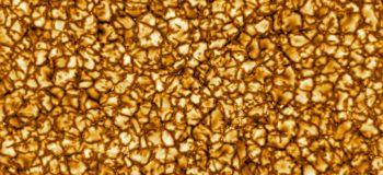
Splashed across my newsfeed today were the first pictures taken by the brand new Daniel K. Inouye Solar Telescope in Hawaii, showing the highest ever resolution pictures of the sun. The pictures are incredible: the images show a network of bubble-like convecting plasma cells, each of which is roughly the size of Texas:
The fluid-dynamicists amongst us might recognize this pattern as a Bénard convection cell which happens as a consequence of natural convection in a liquid (or in this case a plasma) that is heated from below. Basically, the same thing that happens when you heat a pan of soup, which is best served hot, but not as hot as the surface of the sun:
A few years ago I was lucky enough to interview some of the engineers that (with the help of Simcenter) designed the cooling systems that, despite obviously huge solar loads, keep the surface of the temperature of the telescope’s mirror so cool that you could touch it (although that’s probably a bad idea).
World’s Largest Solar Telescope
Completed just a few weeks ago, the 41.5 m tall Daniel K. Inouye Solar Telescope (DKIST) is the world’s largest solar telescope. The DKIST is intended to provide the sharpest views ever taken of the solar surface, which will allow scientists to learn even more about the Sun and solar-terrestrial interactions. The DKIST will allow astronomers to resolve the extremely small, violently active, magnetic fields that control the temperature of the corona and the solar wind that produce flares and x-ray emissions, and help to improve prediction of the way these “space weather” phenomena influence the earth.

The telescope is built atop the Haleakala volcano on the Pacific island of Maui, which was chosen from a list of 72 possible global locations after 2 years of monitoring daytime seeing conditions. Haleakala has the darkest clearest skies, and its tropical location and elevation mean that the telescope sits above the turbulent inversion layer so there is little turbulence to blur its view or moisture to block the infrared spectrum.
At the heart of the telescope is a huge 13ft (4m) primary mirror which, when combined with adaptive optics technology that reduces the amount of blurring from Earth’s atmosphere, produces images 33 times sharper than those of common telescopes. The resolution of the DKIST is comparable with space telescopes, but at a much lower cost and with the benefit of greater accessibility. Unlike a space telescope, it will be relatively easy to upgrade the technology of the DKIST throughout its lifetime.
Blasted by the Sun
A solar telescope-specific problem is the heat generated by the tightly-focused sunlight. Unlike most large ground-based telescopes, which are used at nighttime to capture a small number of photons from distant astronomical bodies, the DKIST will spend its working life pointed directly at the sun, absorbing large quantities of focused light and heat energy.

A Heat Stop is an integral part of the design of solar telescopes and represents one of its larger engineering challenges. It performs the role of what is called a “field stop” in a conventional telescope, limiting the field of vision to the area with minimal distortion. Located at the prime focus, the Heat Stop prevents unwanted solar disc light from heating and scattering on subsequent optics. In a solar telescope such as the DKIST, in addition to blocking light, the Heat Stop must also dissipate huge amounts of thermal energy.
For the DKIST, the heat load is 2.5 MW/m2, reducing the heat load on subsequent optics from an enormous 12 kW to a minuscule 300 W (a reduction factor of 40). Designed by Aavid Thermacore, the Heat Stop Assembly is actively cooled by an internal system of porous metal heat exchangers that dissipate approximately 1,700 W at peak operating load.
The Heat Stop must not only be able to survive this heat load (without cooling, the Heat Stop reflector would last only about 30 seconds before catastrophic failure) but also must remain cool enough not to induce any additional turbulence inside the telescope’s dome.
Self-induced seeing
One of the obstacles of ground-based astronomical observatories is a phenomenon known as “self-induced seeing”. It consists of the degradation of image quality, mostly resulting in an increased blurring of objects and a reduction of contrast in long exposure images. This occurs when thermal and wind disturbances create fluctuating layers of refractive indices within the optical beam path. With this in mind, a small hot object in close proximity to the secondary mirror could have potentially disastrous consequences for the accuracy of the telescope. A key requirement for the system is that the surface temperature of the Heat Stop must never be more than 10°C higher than the temperature of the ambient air so as to prevent buoyancy-induced flows from creating turbulent disturbances that would result in “self-induced seeing”.
As part of the design process, the team at thermal management specialist Aavid Thermacore (part of the Boyd Corporation) was required to demonstrate the efficacy and robustness of their Heat Stop cooling system across the full range of potential operating conditions, as well as in some “failure mode” scenarios in which the failure of some other component had resulted in the telescope being aligned outside of its design range.
The surface temperatures (and generated flow around the Heat Stop) depend on a number of interacting physical phenomena. In simulating the Heat Stop assembly, the engineers had to take into account multiphase flow within the porous metal heat exchangers, conjugate heat-transfer through the Heat Stop assembly and the interior wick structure, and both natural convection and radiation heat transfer around the Heat Stop.
So cool you could touch it
The past decade has witnessed significant growth in the number of applications for a new category of heat transfer devices known as “porous metal heat exchangers”. These devices, when used in conjunction with a pumped single-phase coolant or a pumped gas, take advantage of a porous layer of a thermally conductive medium located beneath the heat transfer surface to effect efficient heat transfer. In this device, convective heat transfer to the selected coolant combines with the “fin effect” produced by the large surface area of the conductive porous structure to produce efficient heat transfer. A porous media heat exchanger can be used to dissipate very large heat fluxes, such as those encountered in this solar telescope, or can be used to provide very efficient heat transfer at much lower heat fluxes.
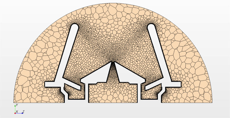
The increased surface area, however, is obtained at the expense of increased flow resistance or pressure drop. To overcome the constricted flow paths, multiple closely-spaced inlets and outlets are used. The pore sizes are sufficiently small to prevent a flow “short-circuit” near the walls. The thickness of the porous structure depicted below is typically on the order of 0.020-0.050.
A significant effort has been made in recent years to improve the fundamental understanding of convective forced flow heat transfer in porous metal heat exchangers, which has resulted in improved understanding of governing principles and has thus opened new applications for these devices such as cooling the DKIST solar telescope.
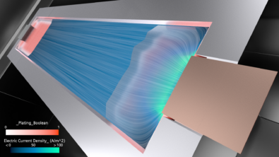
Although some of these configurations provided lower direct thermal loading, Aavid Thermacore engineers needed to demonstrate that asymmetries in thermal loading would not lead to local “hot spots” that might generate additional buoyancy-driven flow patterns (the potential source of a “self-induced seeing” problem). Using Simcenter STAR-CCM+, engineers were not only able to fulfill the design criteria demonstrating that the surface temperature of the reflector could be kept below 10°C above ambient, but they also demonstrated that the criteria were sensible by visualizing the flow patterns generated within the enclosure as a result of natural convection.

Judging by the wonderful photographs released today, it seems that they were very successful in their efforts.