What’s new in NX for manufacturing (January 2019)?

The latest release of NX for manufacturing (January 2019) introduces new and enhanced capabilities for a wide range of applications, such as mold and die manufacturing, production machining and multi-axis milling. Meanwhile, the integrated additive manufacturing functions help you to design, prepare and print breakthrough products that were simply impossible to manufacture using traditional technologies.

Mold & Die Machining
The latest capabilities in NX CAM software will help you to machine higher quality molds at very high speeds that can significantly reduce the machining time.
High-speed Adaptive Milling enhancements
A number of enhancements have been implemented to Adaptive Milling, an advanced operation for high-speed roughing in NX CAM.
 The Bottom Up Cutting is a rest milling type roughing, where the milling is being done from the bottom to the top. It ensures consistent and evenly distributed stock on tapered and contoured walls. This feature is very useful for milling 3D part shapes like mold inserts and cavities.
The Minimum Cut Depth lets you specify the minimum amount of the flute length that engages the workpiece in order to create a better milling process, resulting in less chatter and less tool wear. Since the milling process is more stable if there are more contact points between the tool and workpiece, it is beneficial to set a higher Minimum Cut Depth when machining harder materials.

The Pillar Cutting is an innovative way to address a common issue with high-speed cutting strategies that can leave a small uncut pillar. If the pillar is machined using traditional methods, it can start bending instead of being cut, resulting in getting work hardened. This can increase tool wear and damage the tool. Even worse, the remaining pillar can get ripped off, leaving small cavities on the machined part. NX CAM software will automatically identify the pillars and you can select the best cutting strategy to remove the pillars, such as helical toolpath. By using this new capability, you can extend tool life and improve the overall machining process.

Finishing using Guiding Curves
Guiding Curves is a new finishing operation in which the pattern is driven by one or two sets of curves or guiding curves.
The two main methods to control the cutting pattern are:
Morphing – in which the pattern is evenly interpolated between the two curves
Constant Offset – which creates cutting passes by offsetting the guide with constant stepovers
The generated cutting passes are smooth and they follow the natural geometry shapes, resulting in excellent surface finish that eliminates the need for additional rework.

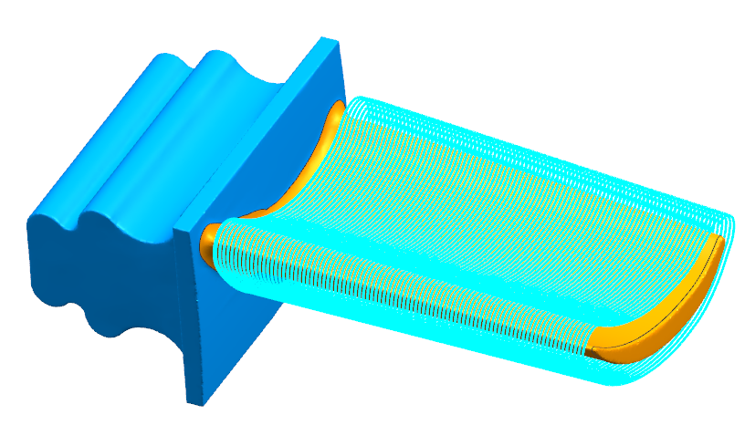
Helical and Spiral Finishing
The new finishing methods in NX CAM software are designed to generate optimized toolpath for specific types of cut regions. The Helical toolpath that is gradually stepping over is a perfect cutting strategy to machine high-quality parts with steep walls.

Whereas, the spiral milling is ideal for machining shallow symmetrical part regions. These advanced finishing techniques deliver consistent stepover and they eliminate sharp stepover moves, which improves the surface finish.

Prismatic Parts Machining
Production machining covers general machining of prismatic parts, such as components for machinery and automobiles.
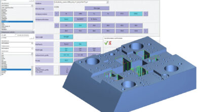
Feature-based Machining
The robust feature-based technology in NX CAM software has been enhanced with new capabilities that streamlines the definition and re-use of best practices using enhanced interactive technology.
In addition to the fully automated methods, you can now select the desired machining process for recognized features using the new Operation Set Based option. The available sets can be filtered based on feature type and criteria, such as hole diameter. In addition, tool selection criteria can be used to automate the selection of the right cutting tools from the library.
This new capability gives you more flexibility when using feature-based machining. You can define, organize and re-use your preferred machining methods, allowing you to automate CNC programming and achieve repeatable results.

B-axis Continuous Turning
Siemens NX software now lets you define tool variable axis orientation to tackle complex parts that would require multiple operations and tools if using traditional methods. Two interpolation modes (absolute and relative) give you flexibility to program challenging parts using modern mill-turn machines, which combine profile turning with continuous tool axis orientation. The new B-axis turning can help you reduce the number of setups, operations and tools, which can dramatically improve your productivity.

Turning using Multi Tools
You can now take advantage of multi-tools to improve turning efficiency. Using NX modeling functions, you can define multi-tools used for lathe operations. Once defined, you can export the tool’s 3D solid model into your tool library and use it for CNC programming of a wide range of turning operations. NX CAM’s integrated G-code driven simulation, lets you simulate material removal, as well as perform collision checking, which is important when using multi-tools that can have complex geometry.


Complex Parts Machining
Five-axis machining in NX enables you to produce complex parts with fewer operations and setups – reducing cost and delivery times. The latest release of NX CAM software introduces new advanced capabilities that streamline the CNC programming while creating efficient multi-axis toolpaths.
Five-axis Finishing Using Guide Curves
Variable Axis Guiding Curves is a new finishing operation that works on any number of surfaces including undercuts. You can use a ball tool (or spherical mill) to create various patterns without projection. The available cutting methods include morphing between multiple guide and constant offsets from a single guide curve. A helical pattern can be also generated when using closed curves. To precisely control the tool axis, you can limit the tool tilting using a 3D curve. This operation also enables automatic tool holder avoidance and tool axis smoothing for safe and efficient 5-axis machining. With this new 5-axis operation, you can finish the most challenging part geometries using smooth toolpaths to achieve excellent finish.

Multi-blade Parts Machining
The specialized Turbomachinery milling operations have been further enhanced with a number of powerful capabilities. You can now set a custom offset at any point location along the toolpath, which enables adaptive machining processes. It can be used for blade repair or to create a blade at the nominal value. In the latest release, NX Turbomachinery Milling helps you generate smoother cutting patterns when machining blisk with non-rotational hubs.

To avoid marks on machined parts, you can control tool axis changes to smoothen the tool moves. This not only improves the surface finish, but it also eliminates accelerations and decelerations, resulting in reduced machining times.

The new multi-stripes blade finishing allows you to machine blades in sections, thus minimizing the forces applied on the blade during the machining.

Using the new roughing settings, you can improve the slotting through uncut material. For example, you can use alternating two passes to reduce the tool load and extend the tool life.

Merge Operations
Often, machining of complex geometries requires use of multiple operations, which can result in inefficient machining or surface finish with visible marks where the operations meet. In the new release of NX CAM software, you can create multiple operations and then merge them into a single operation. There are many use cases when this capability provides advantages.
For example:
- You can merge semi-finish and finish operations. This allows you to create a single operation that will perform both semi-finish and finish on one level, before proceeding to the next level, resulting in improved machining.
- Also, you can merge two or more finish operation operations into a single operation that will result in higher quality surface finish.
NX CAM software lets you save the newly-created merged operation, so that you can re-use the optimized toolpath. The merging function gives you more flexibility, enabling you to define the best way to machine parts.

Leverage Barrel-shaped Tools
Manufacturers increasingly use barrel-shaped tools because they provide important advantages. Specifically designed for five-axis milling, barrel tools allow a large cutting contact with the workpiece. This will enable you to achieve the desired finish quality with significantly fewer passes. With NX CAM software, you can now easily define and use barrel tools to program 5-axis machining operations. By using barrel tools you can dramatically reduce your machining time, while improving the surface finish.

Robotics for Part Manufacturing
The new capabilities in NX Robotic Machining expand the range of applications for this technology.
Robots can be equipped with various devices to perform different tasks, which makes them very flexible. With NX CAM software, you can now program a robot with a drilling head or “quill,” a device used for drilling highly-accurate holes. The process is as follow: after the head gets positioned above the hole using the rotary motions, the robot briefly pauses, and the “quill” performs a precise linear drilling motion. This specialized drilling is particularly beneficial for machining of large parts, such as those used in the aerospace industry.
By using the digital model of the robot and the entire setup, the toolpath finding capability helps you identify Part manufacturers in many countries need to program in inches, but robot controllers require input in millimeters. To resolve this issue, NX CAM now lets you program in inches, and output the code in millimeters to control your robots. We are continuously expanding the support for robotic controllers. Besides ABB, Kuka, Fanuc and SINUMERIK 840D, you can now program Yaskawa, Staubli, Nachi and Kawasaki.

Postprocessing and Machining Simulation in NX CAM Software
The NX CAM postprocessor helps you generate production-ready CNC programs for a wide range of machine tools and controls with a postprocessor embedded in your CAM software. The integrate machining simulation capabilities enable you to accurately validate manufacturing operations to eliminate errors in production and it also helps you reduce setup time and maximize machine uptime.
Postprocessing
The integrated postprocessor in NX CAM software lets you output machine-specific CNC programs. The recently implemented Post Configurator technology provides an easy way to setup your postprocessor in an interactive environment. In the latest release, Post Configurator has been further enhanced to provide support for multi-channel (multi-function) machines. You can now quickly customize the postprocessor to ensure that you output the right code for multi-function machines.
With the new Inspect Tool in Post Configurator, post developers can analyze the post processing, which makes it easy to see the relationship between the variables and events, and the generated CNC program. The latest Post Configurator library is encrypted using the TBC encryption to protect your intellectual property. Lastly, a new 3-axis milling option in the postprocessor speeds up the postprocessing, so you can quickly generate CNC programs for large 3-axis toolpaths.

Machining Process Visualization
Using the new capabilities to display the cutting tool, to animate tool motions and to simulate material removal, you can easily visualize the machining process as you program the part. Note that these visualization and interactive capabilities don’t require you to open other dialogs or to run the full simulation.
From your operations navigator, you can simply select an operation and pick a location on a toolpath. The system will then display the complete tool assembly at that point and you can play the tool motion check the toolpath.
To get better insight into the machining process as you program, you can also visualize the current status of the in-process workpiece (IPW) at the selected point of a toolpath. If you play the tool using the IPW mode, you can verify the material removal process, so you can optimize the machining process.
The analyze command can display additional information about the selected toolpath location, such as the colored display of the remaining material. This powerful visualization functionality helps you get the right toolpath the first time.

Machining Simulation in NX CAM Software
The integrated machining simulation tools in NX CAM software helps you identify possible errors in production using the digital twin of your process and resources. Moreover, it enables you to optimize your machining processes on the shop floor using the new validation capabilities. New simulation and verification capabilities for turning operations helps you to eliminate expensive errors in production, such as collisions between the workpiece and the tool assembly. This capability also extend to multi-tools that can be very challenging to program with if your CAM system lacks automated collision and gouge checking.

You can now leverage color coding to better understand the machining process when using material removal simulation in NX CAM. You can not only assign colors to tool types, but you can also assign colors to each individual tool, so you get a very detailed representation of the process.

Sometimes, it is important to keep a constant speed of the tool tip in order to obtain a controlled machining process. For example, if you do material deposition with an additive laser, you might get too much material added when the tool tip stays at a certain position. Also on a milling machine, you could get a visible mark on the surface if the machine stops at a position. NX software now provides detailed information about tool tip speed, such acceleration, deceleration and constant speeds, using the dynamic axis parameters in the machine tool definition. You can also create a plot of the tool tip speed over time.


To make you more efficient during programming, NX now calculates the in-process workpiece (or IPW) after you create a toolpath. This calculation happens in the background, so you can work on other programing tasks. This enables you to start simulation of any machining operation almost instantaneously.
Improve CNC Programming Efficiency
The comprehensive support capabilities in NX CAM software can significantly accelerate the NC programming process.
CAM Home Ribbon
The CAM Home Ribbon has been reorganized so you have all the programming commands easily available.
A new Geometry Tab has been added to the CAM Home Ribbon has all the synchronous modeling commands and other CAD functions like Point, Extrude and Blend. The Assembly functionality and the WAVE linker are available on that Geometry ribbon as well. Using the commands on this tab will help you quickly prepare the part model geometry for CAM programming.
The Analysis tab has been simplified and is much less crowded. From the updated CAM Home Ribbon, you can access the new toolpath and tool display commands, as well as the tool animation functions, discussed earlier.
The redesigned CAM Home Ribbon enables you quickly access all the go-to CAM commands so you can program your jobs faster.

Support for Convergent Models

You can now program convergent models, which combine solid and faceted geometry. All the additive, and many of the 3- and 5-axis milling operations are now supported.
The following operations support Convergent part models:
- All additive operations
- Guiding curves (3- and 5-axis )
- Area mill
- Flow cut
- Z-level
- Cavity mill
- Plunge mill
- Tube milling
- Tilt tool axis
Below are the operations that currently do not support Convergent part models:
- Multi blade operations
- Planar mill
- Face mill
- Floor-wall mill
- Streamline
- Surface area
- Curve drive
- Cylindrical parts finish
Additive Manufacturing
The additive manufacturing capabilities in NX software facilitate the process from design model to printed part with seamless integration that eliminates the need to convert and remodel parts between applications.
Using the new capabilities in the latest version of NX for additive manufacturing, you can easily print production-quality parts using a wide range of additive manufacturing technologies.
New Support Structure Types and Improved Performance
Different materials and printing processes require different support types. In the past, NX supported various support types like block and wall type support structures. NX now supports tree structure types in addition to those previously existing types.
Furthermore, users can now combine certain support structure types together. This is useful when you want to optimally support a single surface using different support types. Finally, when dragging an existing support structure to change the support angle, the preview generated as you drag is now considerably faster resulting in a much easier interaction during an angle change operation. This is especially noticeable on large or complex support structures.

Improved Support for Multi-body Parts
In past versions of NX software, adding an NX part file with multiple bodies to the build tray resulted in all of those bodies being treated as a uniform part to build. Now, individual bodies in the same part are treated as individual parts such that they can each now have their own individual support structure types and build strategies.
For example, you may place a part with two bodies into the build tray. You can now use block supports for one body and line supports for the other. You may also use different build strategies for each part. This gives the user much more granular control over how the various parts and bodies in the build tray are supported and printed.

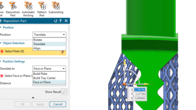
Improved Method for Adding Parts to the Build Tray
Previous versions of NX used the standard Add Component command to add parts to the build tray. However, this mean that NX added parts according to the visibility of the objects, but ignored reference sets and layer settings leading to problems with the build.
The new Add Part command improves this situation by honoring reference sets and layer settings as well as preventing empty reference sets from being added to the build tray and also warning you if a reference set contains a mesh or facet body. This makes adding parts to the build tray much more straightforward and robust.

Multi-axis Printing Improvements
Multi-axis printing has been improved with several new deposition path types. These types mean you can now create smoother 3D output by following a guide surface. You can also now weld or connect parts easier using various new deposition path types. Finally, stronger thin-walled parts can now be constructed with improved start point control. All of this means that the world-class output from multi-axis deposition is better and even more robust than in previous versions of NX.

For more information about the latest version of NX for manufacturing, check out the “What’s New in the NX,” Tech Tips videos.
Watch the video, “What’s New in NX CAM – Mold & Die Machining”