Streamlining machining and quality inspection operations using PMI
Ford Motor Company uses Siemens software with product and manufacturing information (PMI) to quickly and cost-efficiently launch machining lines
A global automaker headquartered near Detroit since 1903, the Ford Motor Company now employs 190,000 at more than 60 plants worldwide. Beyond its renowned role as a truck and automobile OEM, Ford remains deeply involved in automotive component design and engineering, including engine manufacturing. The company collaborates closely with Siemens and it’s solution partners, like Janus Engineering, to launch automated computer numerical control (CNC) machining of new powertrain components.
At Realize LIVE 2020, Siemens’ global customer event Dave Doody from Ford, along with Jerry Lewis from Janus, presented the Ford implementation of PMI using Siemens NX™ software to improve the quality, timing and cost of powertrain component manufacturing launches. This blog summarizes their presentation.
Manufacturing development triple challenge
The interplay of timing, cost and quality makes for a complex challenge for the Ford engineers involved in engine manufacturing launches. The successful launch of an automated CNC machining line involves a large engineering team working concurrently. Competitive pressures require a lean manufacturing planning process so that time is not wasted manually reentering data at every stage.
To address this challenge, Ford employs Siemens NX with PMI that facilitates a comprehensive 3D annotation environment. PMI allows product teams to capture and associate a component’s manufacturing requirements directly with the 3D model and to convey this information to downstream manufacturing applications.
Although PMI is widely available, the idea of replacing 2D drawings with self-contained 3D models has been slow to catch on with engineering teams that design complex engine packages. Detailed drawings are still required for every step of the incremental process, from casting to finished part, and many stakeholders have limited experience interrogating 3D models.
Application of a PMI solution to powertrain manufacturing has been hindered by the uniquely complex set of requirements for high-volume CNC machining of automotive engine components. These machining lines are designed to run unattended, integrated with planned automation instructions embedded in the CNC code. To minimize wasteful material removal, the manufacturing plan must include special design considerations for the incoming casting and must incorporate multi-step machining with in-process coordinate measuring machine (CMM) inspection after each step.
Despite these inherent complexities, the opportunity to develop smarter workflows using PMI motivated Ford to take on PMI implementation in this manufacturing space. Ford’s goal ultimately is to launch the manufacturing process into production with healthy short-term and long-term process capability.
Designing high-volume machining lines
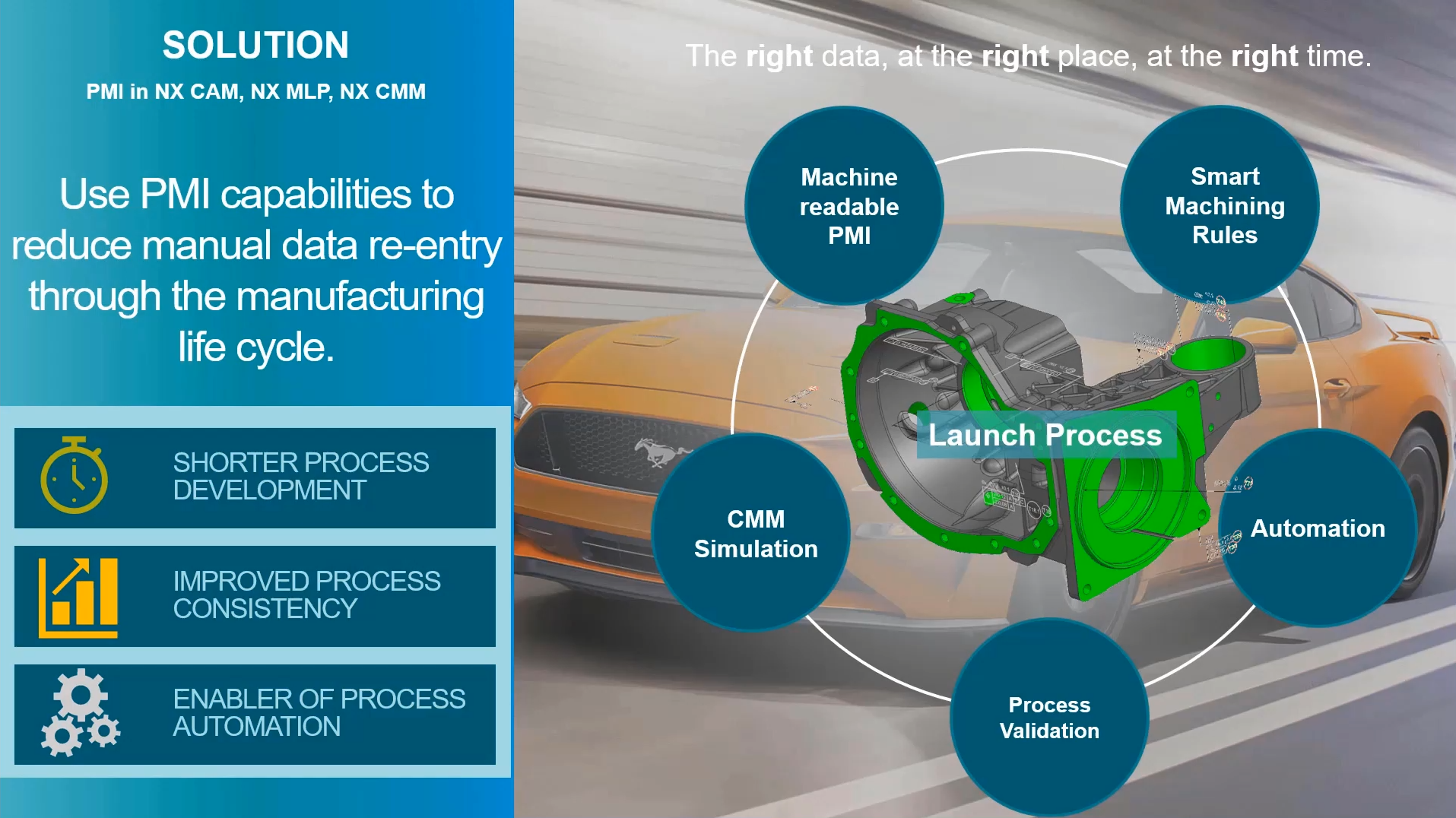
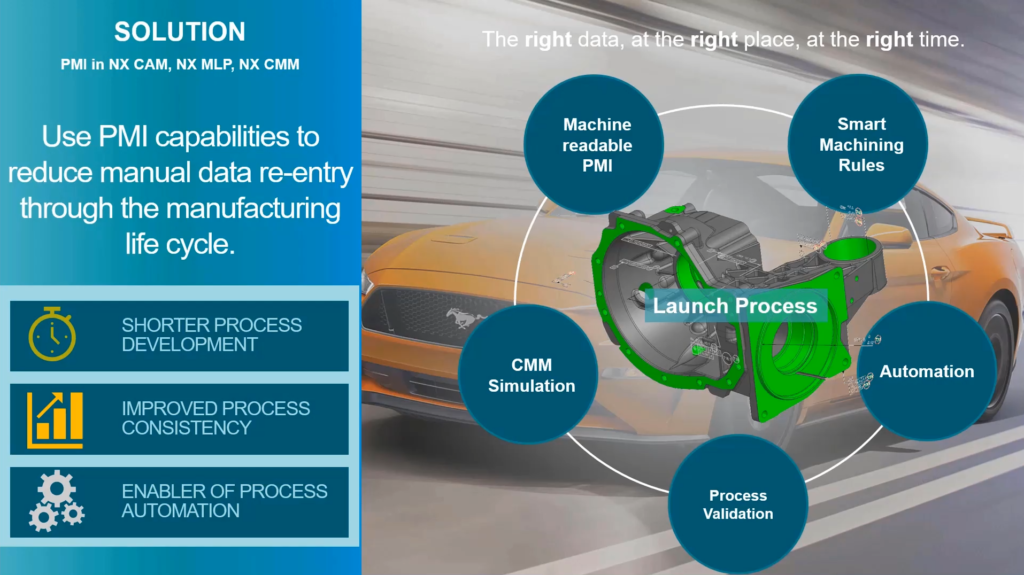
Ford has implemented a model-based definition (MBD) strategy to design the manufacturing and inspection engineering of these high-volume machining lines. This approach uses PMI capabilities in Siemens NX CAM, NX MLP and NX CMM to reduce manual data reentry throughout the manufacturing life cycle.
To develop the machining process for each engine component, the workflow involves multiple machining operations and measurements to accommodate cycle time and fixturing requirements. Geometric dimensioning and tolerancing (GD&T) of compound features specify diameter, depth and position relative to multiple data reference frames. Using PMI, a small engineering team first evaluates component features for process sequence, special tooling, fixture datums, stock allowances, cutting parameters and cycle time requirements. The initial process plan serves as a baseline into which details and refinements are later added by the full engineering team.
Machine-readable PMI is available throughout the process. Smart machining rules use PMI to create CNC code based on tolerance magnitudes. Automation creates standardized in-process dimensions that can be validated automatically in a feedback loop prior to flowing into the CMM simulation phase.
Gaining CAM efficiencies
For the Ford powertrain manufacturing engineering team, PMI information enables faster and more consistent CAM decisions. Key Siemens NX systems supporting the PMI-based CAM process include:
- Creation of optimized toolpaths using the NX Machining Knowledge Editor (MKE), reflecting information embedded in the 3D model
- Generation of 3D in-process models that represent the as-cut condition, using the capabilities of NX Machining Line Planner (MLP) to validate the entire line
- Customization using the NX Open API to fill in the gaps so that in-process PMI tolerances can be created using mathematical stack-ups
The workflow encourages reuse of PMI contained in the 3D model. Steps involving PMI are spread throughout the process and touch multiple workgroups, including design engineering, process engineering, tool design, fixture design, CNC programming, CMM programming and launch to production.
Critical documentation is created through NX Open API automation, including:
- PMI representing in-process tolerances required after each operation
- Plan and section views for each tool
- Features labeled with names extracted from the machining feature navigator
- Critical cutting dimensions for each tool
- In-process feature control frames
The work at Ford assures that all team members get PMI as designed, validated and optimized to enable PMI machine consumption in downstream manufacturing and quality applications.
Streamlined CMM programming
Ford uses PMI information to create CMM programs integrated on the machining line. The Siemens and Janus PMI solution has saved 50 percent or more of typical CMM programming time using interactive input of tolerances. Ford programs and employs various measurement devices on their high-volume powertrain component machining lines, including on-machine CMM probing, in-line inspection with a programmable gauge, and a 5-axis scanning probe system.
Capitalizing on the PMI-based master model definition they have developed, Ford uses NX CAM/CMM integration for its inspection engineering. The team adds PMI to each of the in-process workpiece (IPW) stages for in-process inspection programming. All data is linked via NX WAVE and can be used by NX CMM to program probing and inspection based on master model PMI.
Since on-machine probing can be a relatively slow process, NX CMM software helps minimize the number of probe points needed to verify that the in-process tolerances meet requirements. CMM probing programs are built into NX CAM for machine code simulation.
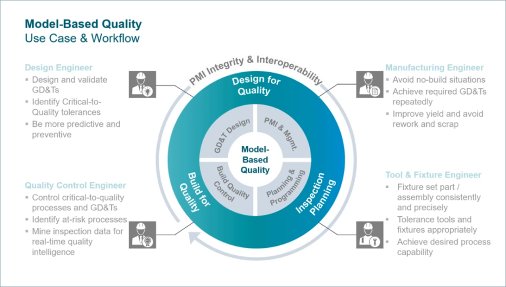
PMI is used throughout the entire workflow to support model-based quality and supports:
- GD&T design and validation
- Model-based design and PMI management
- Machining line planning and quality inspection planning and programming
- Build quality validation and control
Rapid and cost-efficient manufacturing launches
The output of the Ford PMI-based CAM/CMM process is a robust machining plan ready to be launched into production. Using this approach, Ford has achieved:
- Shorter process development time
- Improved process consistency
- Enablement of process automation
Siemens continues to partner with leaders across manufacturing industries to build products and systems that improve sustainability, safety, quality, and compliance, allowing them to better serve their customers, and contribute to a more prosperous world.
—–
