Siemens NX expert shares tooling wizard best practices

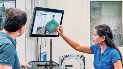
Kevin Jongsma, NX Designer and Programmer, from Intelligent Design and Services, shares his best practices in tooling wizards, Mold Wizard and Die Wizard. Watch this video to get his tips and tricks and let us know what you think in the comment section below.
I design plastic injector molds, diecast dies, and other types of tooling items.
I’ve been coming to Siemens user events for about 12 years. The national event used to be called PLM World. For the local event I was the president of the Chicago-area user group for the past six or seven years. I was involved for 20 years and find this to be very valuable to learn new things and get training.
My presentation at Realize LIVE 2019 was on the twin wizards that Siemens has developed over the years. The products have a lot of similarities between them. I am an expert in the Mold Wizard product. Progressive Die Wizard is very similar although it is a whole different discipline. The architecture is the same. There is also Stamping Die Wizard – a little bit different yet from the Progressive. But, they all have common functions that I highlighted in my presentations, and how they are the same across all of them. I described how to leverage them for the automation ntent that they have.
One of the items I covered in the presentation was the Bill of Materials. Every design has a Bill of Materials for purchasing the different components to build that mold and or die. The Bill of Materials automation greatly reduces the amount of typing, increases the accuracy of the part numbers, material sizes. Mold Wizard and Die Wizard have captured a lot of these descriptions, titles and materials, part numbers, and suppliers. It is all build into the system, so we don’t have to type them repeatedly. Today I demonstrated how easy the automation is and how to leverage it even so far as using it for detailed notes on detailed drawings. The least amount of time I must type it, the less chance there is for error. And, it is all associative, if I make a change in the design, all those sheets will update. The Bill of Materials will update, the detailed notes will update, and that makes me a happy camper!
In the presentation we also covered the pocket command.In the Wizard software, if I were to add a screw into an assembly, it knows the size of the screw and knows the threads of the screw. I can add it between three or four different plates. I can then use the pocket command to automatically cut the clearance holes, the tapped holes, for that fastener and all those plates automatically and associatively. I can move that screw around to different locations and the holes and all the different plates move with it. Using the pocket command also has some other features – I can check to see that all the pockets cut for all my components. I can also use that same feature to add material — a different concept than always cutting pockets in a piece of material, now I can add features to a design by using the same command. I should how do use a taper lock where I added material to one side and took away material from the other side, with one common component.
Interacting with standard components
I also showed how to interact with standard components. For molds for example we have progressive components, DME components, and I can select a pillar or a lock and add in my system and going through the menu structure how to change the size, the catalog number, the clearances for a pillar. Sometimes the standard is a 1/16 per side, if your company standard is different you can change it on the fly as you are adding components in to a 1/32 over, you don’t have to go back and touch up your design. These are all interactive before you put the component in. Also, too is interacting with the components, to remove them from the design instead of just deleting them out and breaking all the wavelengths and all different pockets, and different plates, and can remove it through the same interface, and remove it out of the file directory. Another thing in the Mold Wizard and Die Wizard world, there are a lot of components that are not in the library. If we need a component, we download it from the website. We will download a component that does not exist in the software. We bring it into the library and quickly turn that component into a Mold Wizard compatible component to be used as a subtraction tool to make the pockets, attributes for the part name, and the catalog number. I only must do it once. If I need to re-use that part in the future, it has all those things typed in. I also demonstrated how to create a re-use library to retrieve that component.
Tooling Simulation
The Mold Wizard software has a simulation package, with the kinematics of the plates, slides and lifters, and the Progressive Die Wizard has one as well. It has the same interface. So, I can simulate the mold, opening and closing, and I can check for interferences. I can check the part ejecting out of the mold to see if I have enough ejector stroke. If the part comes off the core completely, then I can simulate that in less than five minutes by mounting a few plates. I can do side actions to make sure there is enough stroke. I can get myself out of a bind before it happens. The tool is not very commonly used. It should be used more. It should be used on every job. It is another good tool to check that everything operates correctly.
In a manufacturing environment, there is a lot of pressure to get the designs done. A lot of designers of my age, we can do it all in our heads, we can keep track of everything, and there is a pretty good chances things will be fine. The younger generations will really grasp these tools and will not have to learn all the things that we do, and easily assimilate. The goal of the Realize LIVE presentations, was to say that these are some of the biggest pay backs in the software. I am going to show you how to use it and take them back with you to the shop.
Do’s and Don’ts for Wizards
Don’t rename files in Windows Explorer environment as all the wavelengths will be broken throughout the assembly. Renaming files in Windows takes a hit on performance.
What I really want to highlight are the free tools that are available and helpful, like UG Convert – to convert from an inch to a metric component so you don’t have to go through and remodel something – so it has similar units.
Another good tool is the JT 2 Go – for sharing design information with the shop. It is a complete 3D rendering of JT files of your design. You do design reviews with it. I can have it on my cell phone. I can pull up a complete mold design on my cell phone. If I must answer a question, it is readily available,it’s free and easy. This is just four of five examples of tools but there are 15. These are the ones with the biggest paybacks of Mold Wizard and Die Wizard.