Designcenter NX | Tips and Tricks | Molded Part Designer | Design for Manufacturing
Molded Part Design is a Designcenter NX™ software add-on module that provides a dedicated workspace for the development of injection-molded plastic parts. In our specific project here, we will look at a new clothes iron. In this instance a lot of the work has already been carried out but then has been left by a contract engineer. We need to continue where their work ended, check it, and complete the design.
Watch the video below to see some helpful tips for getting the most from Molded Part Designer’s, or keep scrolling if you’d prefer to read.
Continuing a project
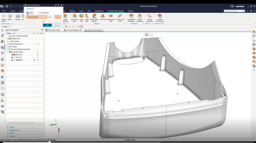
In our example, we have a part that needs to fit around some wires and attach to screw bosses. When taking over an already started project, it’s very useful to open that part so you’re able to examine it more closely. The outer shell is complete, and we can see that several interior ribs have already been created. The contractor also created reference points for the mounting, but it’s not yet designed. This means that the mounting features will need to be created, at the necessary locations.
Checking against company standard
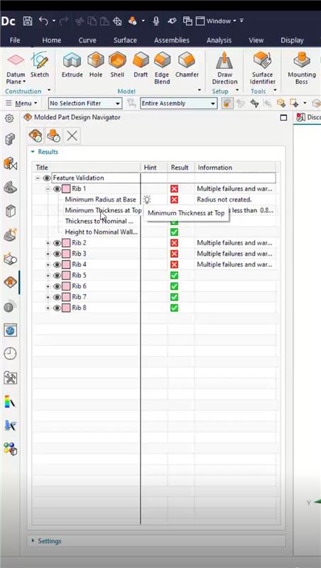
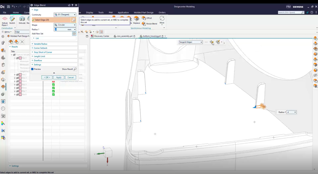
This is an important check when looking at any design, with your company and crucial to future steps you might make within your project. In our example we will begin by defining the mold opening direction so that subsequent commands can consistently use it, and confirming the checking parameters are set up to our company standards. The contractor sent this part as a STEP file, so there are no CAD features we can use to quickly review the ribs. However, we can use the Feature Validation command to quickly check them. The results show that the four ribs at the back end look good, but the ribs on the sides have warnings. One specifically says that the ribs are too thin, whilst the other denotes no blend at the base and it’s recommending that we can use the edge blend command to fix it. We have no CAD parameters to edit like we mentioned previously, but we can use Synchronous Offset to directly modify the ribs, adding extra material to each of the blends.
AI Driven Selection Prediction
To start, let’s blend along the vertical rib edges. Notice that we only had to select one vertical edge and the AI Driven Selection Prediction functionality found seven similar edge chains. Here, you can confirm its findings and have it to complete the blends. Similarly, when we select one edge of the base of the rib, Selection Prediction finds the other rib change. All ribs now pass the requirements.
Adding additional parameters
Let’s turn our attention to creating some new bosses to use with the mounting screws. We need to make sure we place them at the points provided by the contractor’s model and enter the appropriate sizes. The legend allows us to easily understand what each parameter means. You can utilize whatever you need here, so in this instance, we are going to ask to have ribs automatically created around the bosses because they provide the necessary strength around the screws. We next create two snap joints near the bottom, again, using the points provided and inputting the appropriate values, taking account of the legend to understand each parameter.
Reminder, once these are complete, run the validation again to check that the new features are acceptable.
What if something flags as a warning?
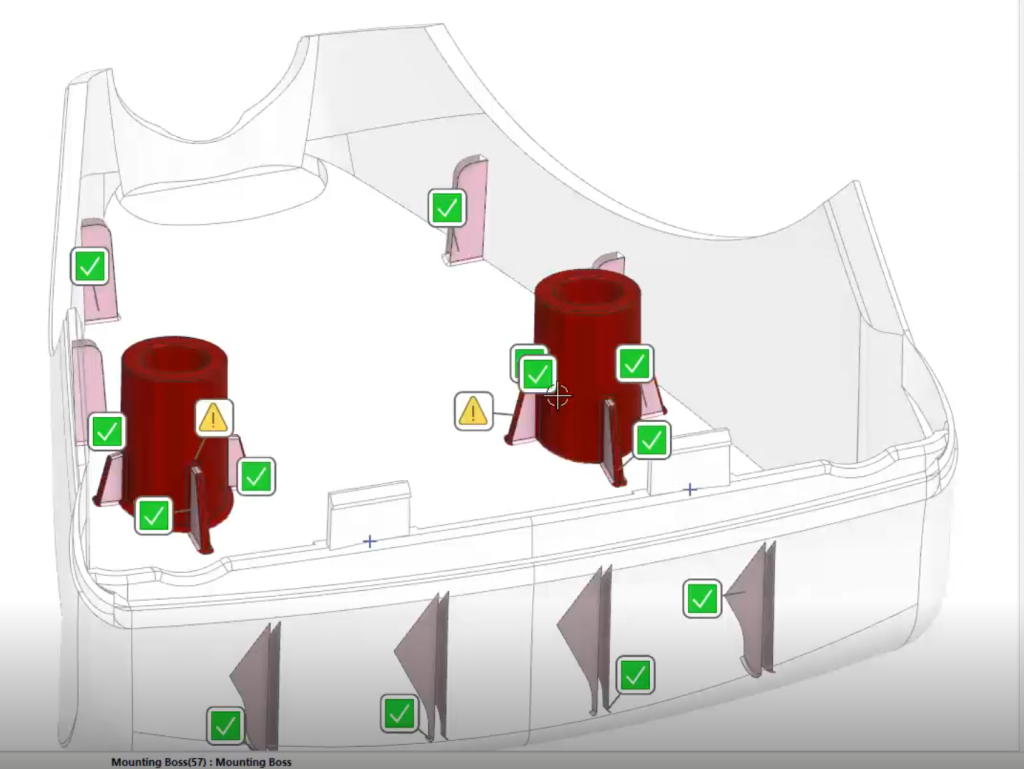
We have been informed here that the snap joints passed, but the mounting bosses show warnings. Let’s select one to see what the issue is. It appears that the base radius is too small per our standards and needs to be increased. We can easily do that by modifying the feature parameters for both bosses. When complete, we will update only the out-of-date validations on the bosses to save time and check again that everything passes.
Utilizing Selection Prediction
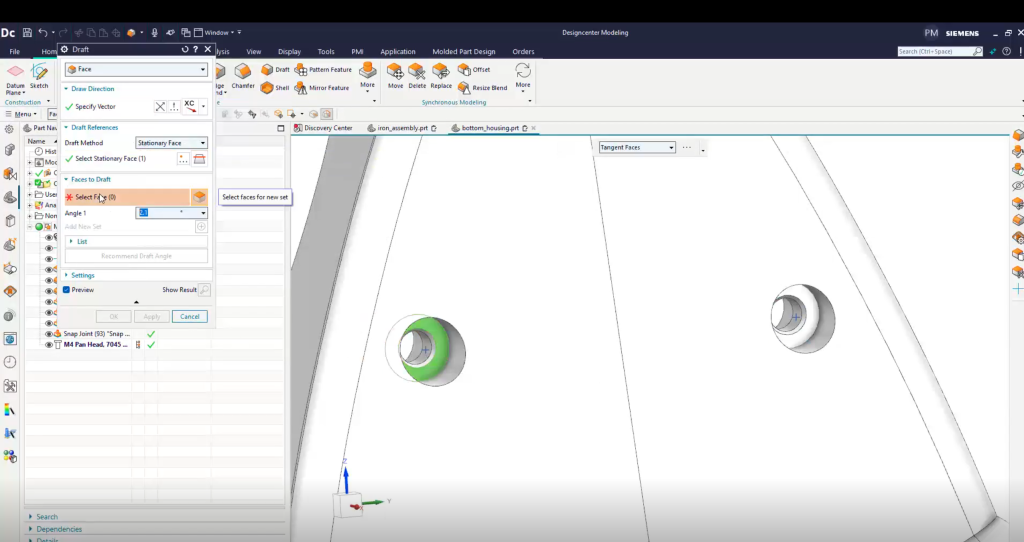
Just a few more details remain on our project. We need to add a hole in the middle of each boss for the screws to fit through and a countersink to accommodate the recess screw threads. We can select the same mounting points used to create the bosses and enter the appropriate parameters for the countersunk hole. Then add draft to the countersunk holes so this part can be correctly molded. Notice here how Selection Prediction is again helping us select similar geometry. In our example, we can ask the command to provide a draft angle recommendation based on the material ABS, and we can use the recommended 2.6 degrees. Finally, let’s add a one millimeter blend around each counter sync again with some AI assistance, and we are finished with our part of the job.
Final thoughts
Hopefully you have found this helpful but utilizing Designcenter NX’s Mold Part Designer! To summarize, we have taken a partially finished part from a contractor and modified some of the ribs, to meet our requirements, added bosses and countersunk holes for the mounting screws and two snap tabs. We also validated all these mold features against our company’s standards.