Don’t design parts with CAD
This may seem an odd statement coming from a product manager for a CAD product, so let me explain what I mean by it.
In the old days, we learnt to work on drawing boards; thankfully the days are gone when we needed to know how to sharpen a pencil correctly or develop a side view from top and front views. Now we learn about sketches and feature dependencies. But have we also lost along the way the skill to design products? Obviously not, as our customers are developing some amazing products, but are we all doing it the right way round and in the most optimum way? On the drawing board we learnt how to create layout drawings then move on to detailed drawings. Now in CAD the work is concentrated on constructing parametric parts and building up assemblies, working bottom-up. Now all companies must solve design challenges top-down, otherwise products would never meet their requirements and components would not come together correctly, but not all have formalized this top-down process inside the CAD system in an intelligent way.
So what I am asking you to do is step back and look at how you are using your CAD tools. Every now and again we should reevaluate how we do things and seek to improve the development and business processes.
The intelligent top-down method of construction entails first defining the geometrical requirements and constraints of the product and laying out its basic form and functionality. These layout or control models are then used to drive the position and key characteristics of individual components. The components can then be detailed and build up into assemblies and the final completed product model.
So what types of top-down methods are available?
The first is known as a control structure or skeleton file. In its simplest form, you work in a single file, first defining the key functional areas of the part and its basic layout and shape. From this skeleton file you extract the defining pieces of geometry and distribute them into individual component files. The defining geometry is then used as the basis of constructing the detailed geometry of parts. 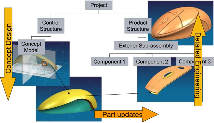 This has the advantage that you can make key design changes in the control file and all components will update accordingly. For example, if you are designing a computer mouse, you would not attempt to build the main housing and individual buttons separately, then hope that when assembled they all fit smoothly together. You would first create the overall shape then define the split lines between components. With the skeleton file process you pass the same overall shape surfaces along with split lines into different component files, then using the split lines, trim the surfaces in different ways to create each component.
The second method of top-down is the zone based method. This is useful when your product contains single components that are large and complex, where splitting the work up among multiple engineers would remove a critical bottleneck in the design process. 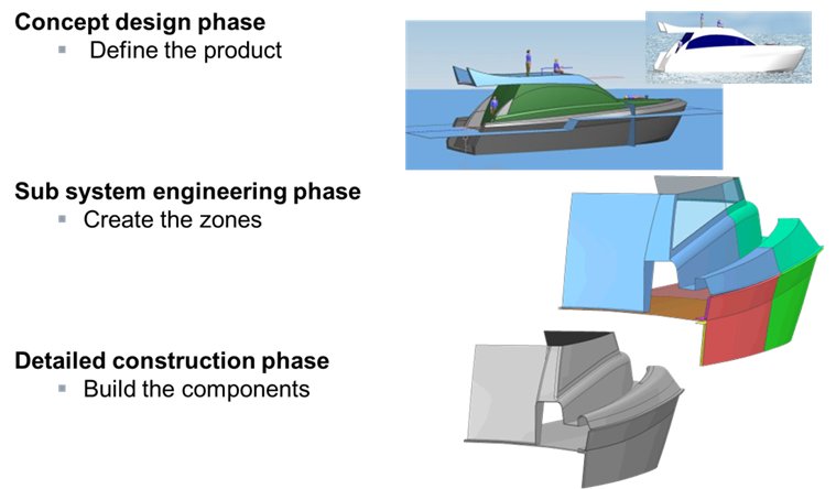 Take for example a medium sized motor boat; the hull, deck and housing consist of only a few parts. The method here again is to start with overall layout and shape files, but then to chop these into zones allowing engineers to work on the interfaces between components in that particular area. When the detail of interfaces and main faces of these zones are complete, they can then be combined into individual components. As the team has all been working off the same layout data, the surfaces will come together correctly.
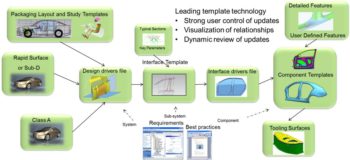
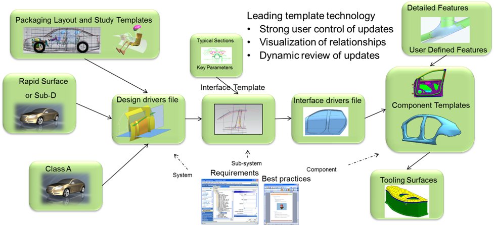
The third method is a variant of the zone method that concentrates on creating an interface file, or files, that are then used to control individual components. The interface files are created from input drivers which themselves are extractions of layout and shape files. This is a technique used in automotive body design for example.
The key drivers are geometry created from packaging layout studies defining fixed points and styling Class A data that are then used to construct the interfaces between key components, which in the case of automotive body in white are the seal faces between all the door openings. From these interface surfaces individual components can be driven.
The advantage of these methods is that design modifications can be made on the whole product and the individual components will adapt to fit. This allows for quicker design changes as well as more thorough experimentation with alternative design solutions.
The key to all of these methods is to design the products, engineer the interfaces and detail the parts.
So what I suggest is take the time to go back to the drawing board (not literally though!). Take a look at your processes and see how you can use CAD to design products, not components.
Eur. Ing Steven Vickers, NX Product Manager