Designcenter NX | How to | Creating Technical Drawings

In our latest Designcenter™ NX™ software Tips and Tricks video we dive into the complete process of creating technical drawings. Whether you’re setting up your first title block, adding balloons to identify components, managing multiple drawing sheets, or updating drawings after design changes, this video covers everything you need to know.
Check out the video below or scroll down to learn more about creating technical drawings.
Getting started with your technical drawings
Creating a technical drawing begins with establishing the foundational elements that ensure clarity and professionalism—critical factors that accelerate review cycles and reduce costly manufacturing errors. The first step is setting up the title block, which serves as the authoritative source of project information.
Once you select a drawing specification, Designcenter NX automatically prompts you to enter the necessary information, eliminating manual placement errors. Simply input details like part numbers, revisions and designer information, and the software intelligently places these entries in their predefined locations within the technical drawing, ensuring consistency across all your documentation.

The next essential step is incorporating a Bill of Materials into your technical drawing, which streamlines procurement and assembly processes. After positioning the BOM, you can extend and expand it for optimal display that enhances readability for manufacturing teams.
To visually link the BOM to your components and eliminate confusion during assembly, display balloon callouts by right-clicking on the exploded view border and selecting “Show Balloon.” This action automatically generates balloon IDs that correspond to your Parts List entries, making individual component identification straightforward and intuitive while reducing assembly time and errors.
Managing dimensions and tolerances
Precision is paramount in engineering, and Designcenter NX provides robust tools to ensure your technical drawings reflect this standard—minimizing rework and ensuring parts fit correctly the first time. As you work through each view, apply appropriate dimensions along with proper tolerances to clearly communicate your design intent to manufacturers and suppliers. Designcenter NX makes it easy to create various types of dimensions and tolerances within your technical drawings, ensuring accuracy at every step and reducing the risk of misinterpretation.
Once you’ve updated your sheets or views, you can project dimensions and tolerances into other views, guaranteeing that every aspect of your design is precisely defined and consistently documented across all technical drawings—creating a single source of truth for your entire team.
Layer control and organization
A well-organized technical drawing is a clear drawing, and Designcenter NX offers powerful layer control and organization capabilities to help you achieve this, saving time for both designers and those who rely on your drawings. Layers allow you to categorize different types of drawing information and create organized views within your technical drawing that focus attention on what matters most.
For example, many engineering organizations move standard components like fasteners to specified layers as a common practice, reducing visual clutter and improving drawing comprehension. The Layer Visible in View option is particularly useful for maintaining clarity—after adding a view, simply select it and turn off non-essential layers to ensure only the relevant components are visible, helping reviewers quickly understand the design intent.
Strategic use of drawing sheets is equally vital for managing complex technical drawings and keeping information digestible. You can insert additional sheets into a drawing by right-clicking on the Drawing in the Part Navigator and selecting “Insert Sheet.” Sheets are typically kept consistent in size, and you can create multiple sheets to separately manage assembly views and detail views, preventing information overload.
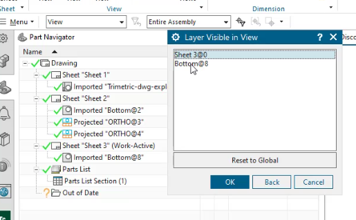
When creating detail views of components, you have two effective options: use parts already loaded in the session, or leverage the Layer Visible in View option, which becomes especially powerful when layers are specified for all components and can dramatically speed up your workflow.
To synchronize component layer settings from “Original” to your defined layers, select the sub-assembly, right-click for properties, and then choose Layers, Display, and Attributes under the Synchronize Subassembly Properties listing in the Assembly Tab.
Updating your technical drawings as your design evolves
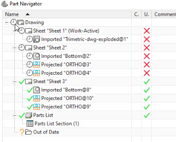
Design is rarely static, and Designcenter NX is built to handle design evolution seamlessly, ensuring your technical drawings always reflect the latest design without manual tracking. When design changes occur the technical drawing will display an “out of date” icon represented by a clock in the Part Navigator, preventing outdated drawings from reaching the shop floor.
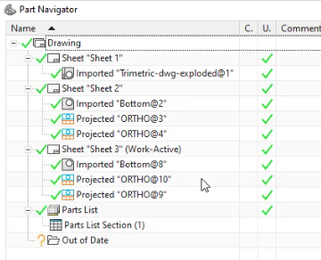
Updating is straightforward: simply double-click the Drawing clock icon to update all sheets and views at once, saving valuable time. Alternatively, if you prefer a more controlled approach to verify each change, you can review changes sheet by sheet and preform updates for each individually.
Managing revisions is equally streamlined in Designcenter NX, creating an audit trail that satisfies quality management requirements. You can insert a Revision Block using the Tabulated Note function, make minor adjustments to column widths as needed, and then position it on your technical drawing sheet.
This systematic approach ensures that all design changes are properly documented and reflected in your technical drawings, maintaining accuracy and consistency throughout the entire product lifecycle while supporting compliance and traceability needs.
Continue your journey with Designcenter NX
Watch the Building an Assembly How to video here ▶️
Watch the PMI Tips & Tricks video here ▶️
Take me to the NX design blog 📚