NX Composites: Part One | Tips and Tricks
Welcome back to the latest entry into our NX™ software tips and tricks series. We’re delving deeper into everything associated with the December 2022 release of NX. Our continuous release cycle means we are consistently adding new functionality to NX based on feedback from you, our users.
Our previous entry into the series looked into Design Space Explorer. If you missed it, check the video out by clicking the YouTube link 👉
Now, onto this weeks’ episode!
An introduction
In this episode, we are going to take a look at using Composites. This will be a two part series; be sure to check back for the second entry next week. Firstly, let’s remind ourselves what NX Composites actually means.
NX COMPOSITES | A DEFINITION
Design a composite part directly inside NX, whilst simultaneously assessing product validity and design for manufacturing. It’s an integral tool to use in your workflow, as you can maintain complete control over the composites you create, whilst also being able interrogate the composite definition with design stations and cross sections.
Define the layup surface
Throughout the course of this episode, the part in question will be a roof panel, and the focus is to investigate the feasibility of producing the part using composite materials. Before applying the correct composite material, there are a handful of steps to consider to ensure your part is optimized. We first need to define the Layup Surface.
To do this, we will need to use the composite’s application with NX and define the layup surface. It’s a fairly straightforward process; all you need to do is navigate to the Composites option in your toolbar and select Layup Surface from the options available to you.

Define the composite region
With the previous step taken, you’re now ready to define the composite region by selecting the Layup Surface. A vital tool to use in your workflow is the Rosette; the Rosette is used as a co-ordinate system for fiber directions, which is essential later on if/when you want to conduct a producibility simulation. Click on the Rosette, and you will be given a couple of options. We’ve explained these options below for you to ensure you choose the correct option for your workflow:
Translational
This allows you to select a point on the face for the origin and rotate the co-ordinate system.
Standard
This option gives you the standard controls as opposed to rotating the origin around a co-ordinate system. You’ll have complete control over the Origin, whilst being able to select a Zero Direction for your material.
In this particular use case, we have chosen the Standard option.
Defining and selecting the laminate
With the Rosette now defined, you’re now in a good position to be able to define the laminate. This is a fairly easy step; all you need to so is navigate to Laminate in your toolbar and select both the Layup Surface and the Rosette from the options presented.
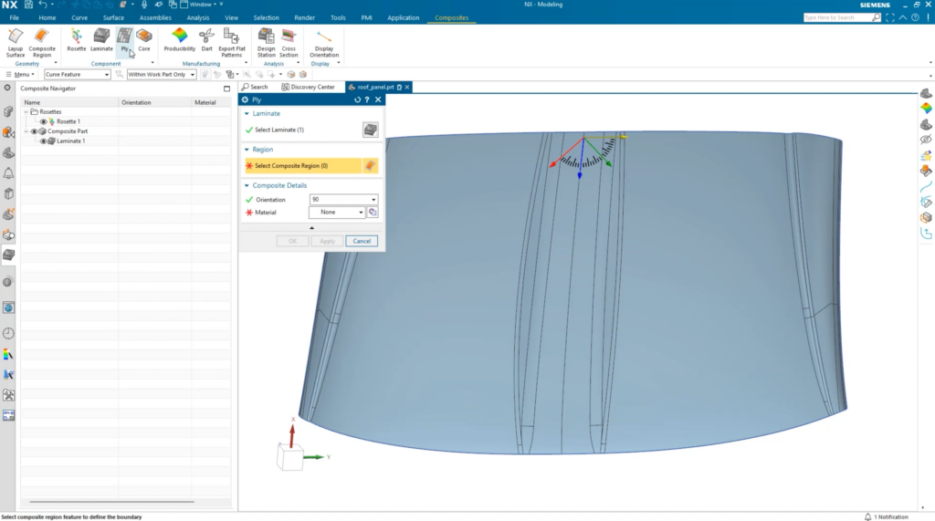
You’re almost ready to start applying your composite material, but there’s one final step before doing so. You need to ensure that you select and set the orientation of the Ply layer to complete your laminate. Again, it’s a fairly simple step; simply go to your Composite Navigator and select Ply. The laminate will be selected automatically, and you can select the region, and finally select the orientation of the ply.
THE DEFINITION OF PLY
Plies are pieces of composite material within a laminate. Plies define an area that must be covered with composite materials of a particular orientation.
Creating a composite material
We’re now ready to start working up a composite material for our roof panel. It’s important to remember that creating your own composite material from scratch ensures you can maintain complete control over what you create, thus enabling you to create a more accurate material in the process. When creating your composite material, there are a range of settings you can control. Let’s take a look:
Naming your material
It goes without saying, make sure you give your composite material a suitable name. In this demonstration, we have named the material ‘woven composite’.
Form
This enables you to select the type of composite material you are creating. Again, choosing your form is dependent on the desired effect you are aiming for. For this specific use case, we have chosen the woven option.
Shear Limit
The Shear Limit is an important tool; it allows you so choose how much the material will stay on the surface during production. For this use case, we have settled on 35 degrees.
Once you’re happy with the settings you’ve chosen, select apply to create the ply layer.
REMEMBER
If the composite uses the same material, you can change the orientation and repeat the step as many times as you desire until you have the layers you need.
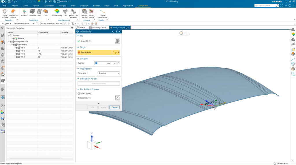
Performing a producibility simulation
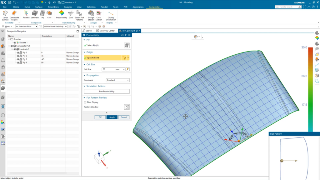
It’s always important to see the producibility simulation of any plies that you create, and NX makes it easy for you to do this. To do so, select Producibility from your toolbar, choose a ply from the composite navigator and then a point on a surface. In our use case, you can see that the arrow shows the origin direction of the weave. For this layer, the weave is set to 0 degrees. The cell size can automatically be determined based on the objects you’ve selected, but for this use case, the cell size has been set to 50mm before we run the simulation.
Examining your results
Once the simulation has completed, we can examine the results to determine the producibility of the ply. The good news is that there are no regions on the ply we have created, meaning the ply can be produced using the material. It’s important to do this with each ply later to ensure they are all fit for purpose. Before moving on, you will notice that the weave direction also follows the angle dictated by the Rosette; make sure to bear these elements in mind when creating your own composite materials!
REMEMBER
If you just want to view a single layer, hide the layers you don’t need to see and select a layer from your Composite navigator
Conclusion
And that concludes the first part of our Composites tips and tricks episodes. In this episode, we covered:
- Defining your layup surface
- Defining the composite region
- Defining and selecting the laminate
- Creating and applying your composite material
- How to perform a producibility simulation
- Examining your results
We look forward to bringing you the second episode on this topic. Stay tuned!
Continue your journey with NX
NX Composites : Part One | NX Tips and Tricks YouTube Video

Comments
Leave a Reply
You must be logged in to post a comment.
Does not create 3D bodies. Only section views.