Designcenter NX | How to series | Enhance your simulation analysis with Performance Predictor

For our latest Designcenter NX™ software How to video, we’re taking a look at features you can use to refine your material selection and improve your simulation analysis with Performance Predictor. Performance Predictor is a simulation application that enables you to review the design performance of a part inside Designcenter NX. It’s an important tool to help designers make informed decisions, and explore concepts without the need for phyiscal prototyping.
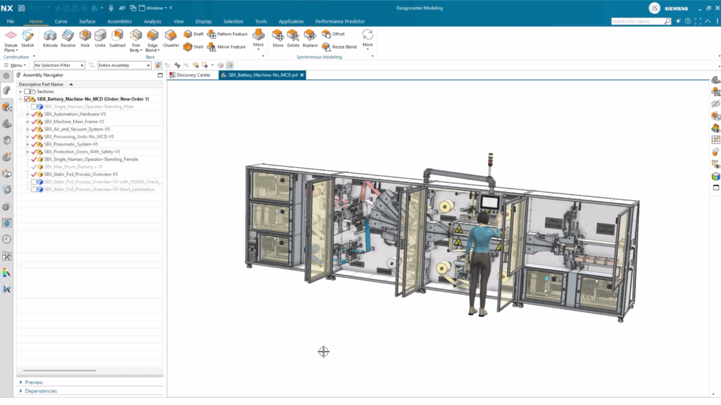
Making updates to the battery machine
The goal for this use case is to allow the designer to be able to make an informed decision as they make updates to the following battery machine. Informed decision in this case refers to using Performance Predictor to determine the feasibility of different metals for our components. We’ll be testing the feasibility of steel and aluminium for the battery machine as shown below.
Before you begin using Performance Predictor, ensure that all analysis bodies are fully loaded, otherwise you won’t be able to select them. You can do this by expanding the component in the Assembly Navigator, right clicking and selecting Open Component Fully. You can also verify that it has fully loaded by checking the current load state.
Starting a new simulation analysis
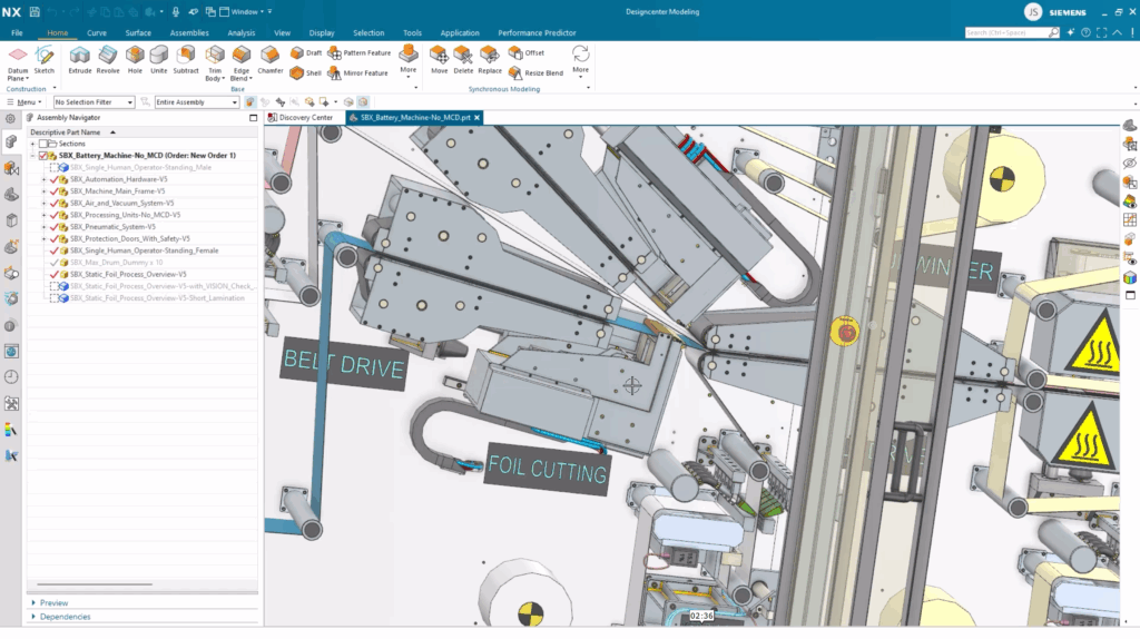
With that important step completed, we’re now in a position to start our analysis, using Performance Predictor. You can use the Show Only command to show only a part that you want to conduct an new analysis for. As we mentioned previously, we’ll be conducting a new analysis for the Foil Cutting Unit.
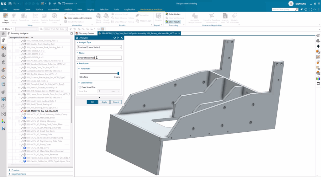
When you create a new simulation analysis from the top ribbon bar, you’ll be given a set of customizable parameters. Here, you can set the Analysis Type, Name of your Analysis, Resolution and the ability to change the Voxel Size. Since this is a rough proof of concept, we’ve left the resolution coarse and left the Voxel Size as the default option.
Any new Analysis starts by defining what you wish to include, so go ahead and select the components for the final study. With your components selected, you’ll notice that the connections between faces will automatically generate. The power of Designcenter NX means you can also edit or create additional connections, giving you complete control over optimizing your components ready for analysis. To do this, it’s as simple as selecting the two touching faces, and a connection will be added.
Setting your simulation analysis constraints
The next step is to set the analysis constraints for your analysis. Setting constraints gives you a greater sense of how the part will behave in the real-world, enabling you to understand the parts predicted performance. What’s more, you can interpret results meaningfully; they give you the tools to calculate stable reference points against potential deformation and calculated stress. They are the foundation of a reliable simulation.
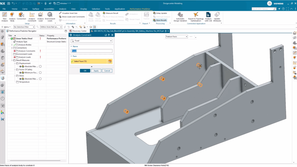
For the Foil Cutting unit, the analysis constraints will be on a set of fixed holes. These holes are for the machines screws that attach this component to the rest of the unit. When we apply the loads, we have several options to choose from.
A Remote Force is an applicable option to choose for this use case since the goal is to simulate the force that will be transmitted through the screws connecting the unit to the rest of the assembly. It’s incredibly easy; all you need to do is Specify Remote Point, Select Target Face and Specify Force Vector.
For the unit, we also need to add additional forces for the foil guides on the cutting tool. Similar to a Remote Force , you can Select Faces, Specify Vector and determine the Force. Additionally, the Distribution across the selected faces. In this instance, keeping it even over the face area is the best option.
Reviewing your Performance Predictor simulation analysis
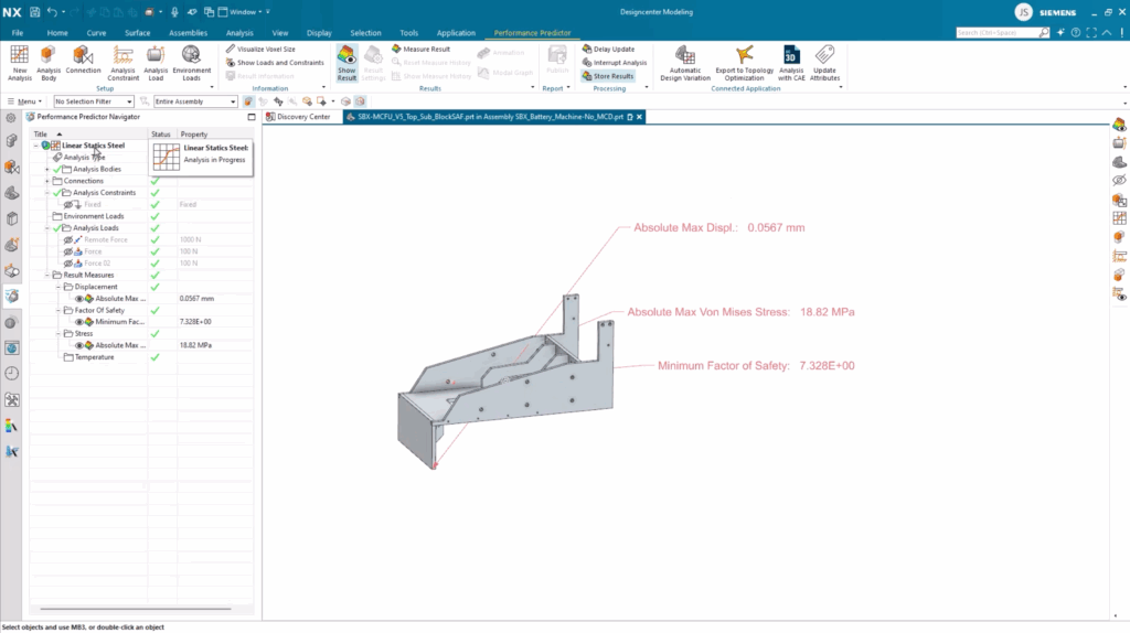
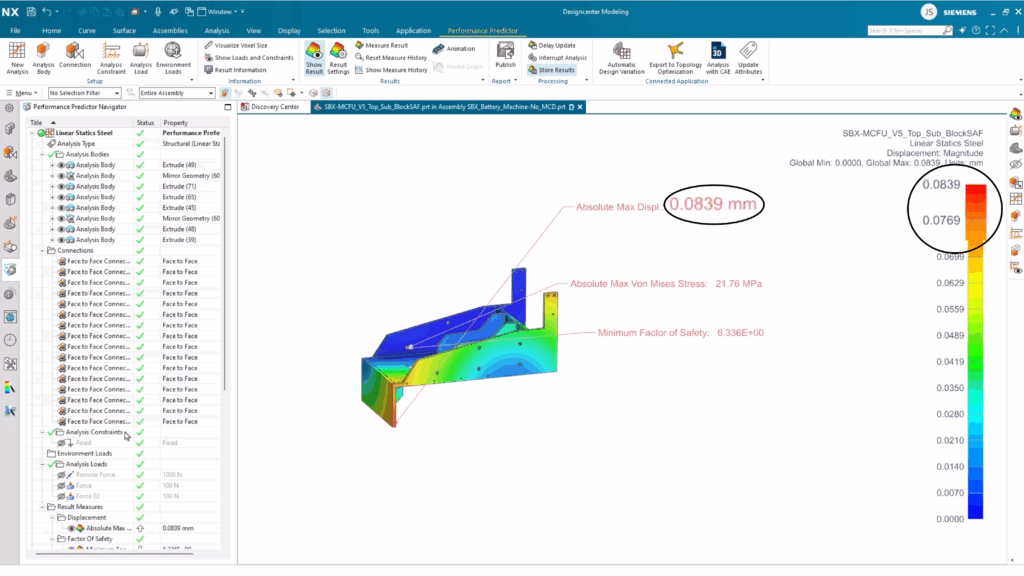
With the analysis parameters running, we can get an understanding of the parts viability. There are three initial parameters which we can see; the Max Displacement, Max Stress, and Minimum Factor of Safety. Each of these parameters are deemed as acceptable, so we can take a look at some other parameters.
Taking a look at the heat map shows the displacement across the part. Anything shown in red is the maximum displacements, whilst blue represents the minimum. Since the initial brief is to compare Steel performance against Aluminium performance, it’s important to make this material change so we can compare.
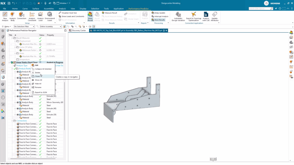
Designcenter NX makes it incredibly easy to setup a new study without having to go back to step one. You can create a clone of a setup and rename it to fit the analysis. For this, the name would be anything that includes Aluminium in the name.
There are 100’s of out-of-the-box materials that can be used and applied to a range of use cases. Since we’re finalizing the Aluminium study, we can select the corresponding material option from the library and apply it to the different components.
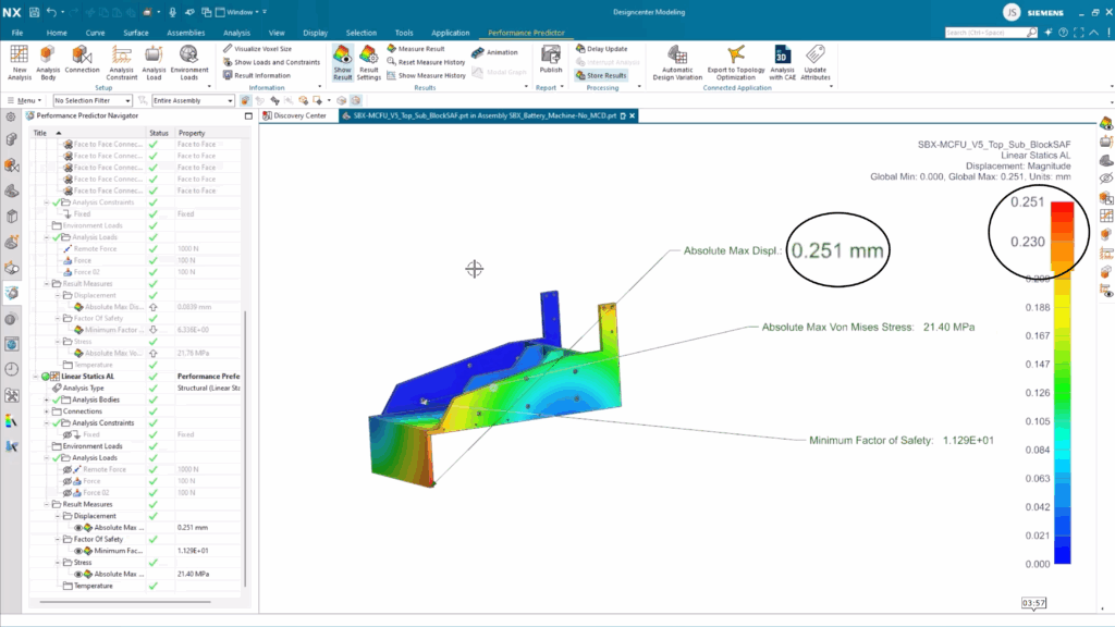
Comparing Steel vs Aluminium simulation analysis
We’ve conducted the necessary steps required to compare the performance of the Foil Cutting unit if we were to use Steel or Aluminium. It’s an easy-to-use, incredibly efficient way of making more informed design decisions, whilst optimizing your constraint parts for manufacturing. Take a look below for a side by side comparison of the two material performances.