Measuring scheduling latency
A topic, that seems to interest many embedded developers, is the performance of an RTOS and how that might be measured. It is certainly a subject which is well received at conferences, where numerous questions are commonly posed.
Broadly speaking, I would rather discourage developers from getting too hung up on the performance figures published by RTOS vendors, as it is incredibly difficult to use them in a meaningful way, but hopefully some guidelines will be helpful …
As an RTOS is, by definition, all about “real time”, it follows that any delays, or “latencies” are of interest to users. Some weeks ago, I wrote about the measurement of interrupt latency. This time I want to think about latency attributed to the scheduler.
There are potentially two distinct scenarios where there may be a scheduling latency. In the first situation, task A is running, an event occurs that causes the scheduler to be run and the context is switched to task B. This latency is made up of three components: context save, scheduling and context restore.

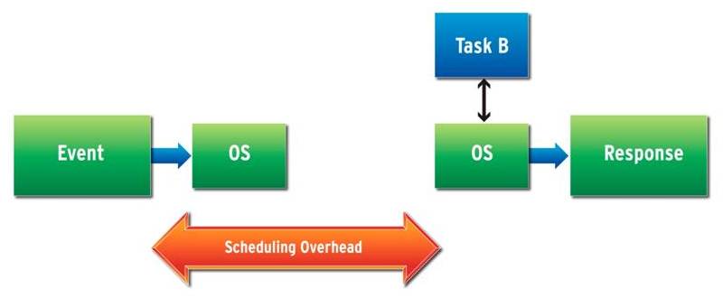
The other possibility is that the CPU is idling, as there is no task that needs to be running, and an event results in task B being scheduled. In this case, the latency only has two components: scheduling and context restore. For some RTOSes this is not relevant, as there is no idle state – it simply runs an “idle task”, which needs its context saved prior to scheduling.
When considering the performance figures provided by an RTOS vendor, it is important to understand which scenario is being measured. The second situation would clearly yield better figures. In addition, there may be other factors that make the figures less relevant to your design:
- which platform and interrupt controller is being used?
- clock speed
- cache configuration
- timer frequency
- what kind of memory is the RTOS running out of?
- was the kernel built optimized for speed?
Of course, it might be more useful to make the measurement yourself. The best way to go about that it to have a GPIO pin triggered by the event and another by the code in task B. These can be monitored on an oscilloscope and the interval determined.
If this topic particularly interests you, a free white paper may be downloaded.