Measuring interrupt latency
I have posted a couple of times recently [like here] about a recent webinar that I conducted on measuring RTOS performance. This is a topic that appears to be of significant interest to most RTOS users, so I thought it might be a good time to pick up on a key detail of the issue.
My colleague Rizwan Rasheed suggested a little while ago that the measurement and specification of RTOS interrupt latency was worthy of discussion …
The term “interrupt latency” is widely used, but, like a lot of technical terms, its meaning is sometimes unclear. This is our first challenge – to define our terms. The second challenge is to make a meaningful measurement.
Most RTOS vendors quote interrupt latency figures for their products. However, they may be referring to either one of two time intervals. In both cases, they are talking about the delay before an interrupt is serviced, but there are two ways to see this:
- System interrupt latency – the interval between the assertion of the interrupt signal and the starting of the code to process that interrupt. This is represented by the long orange arrow in the diagram below.
- OS interrupt latency – the time overhead added by the RTOS to the “normal” processing of an interrupt. This is represented by the short arrow.
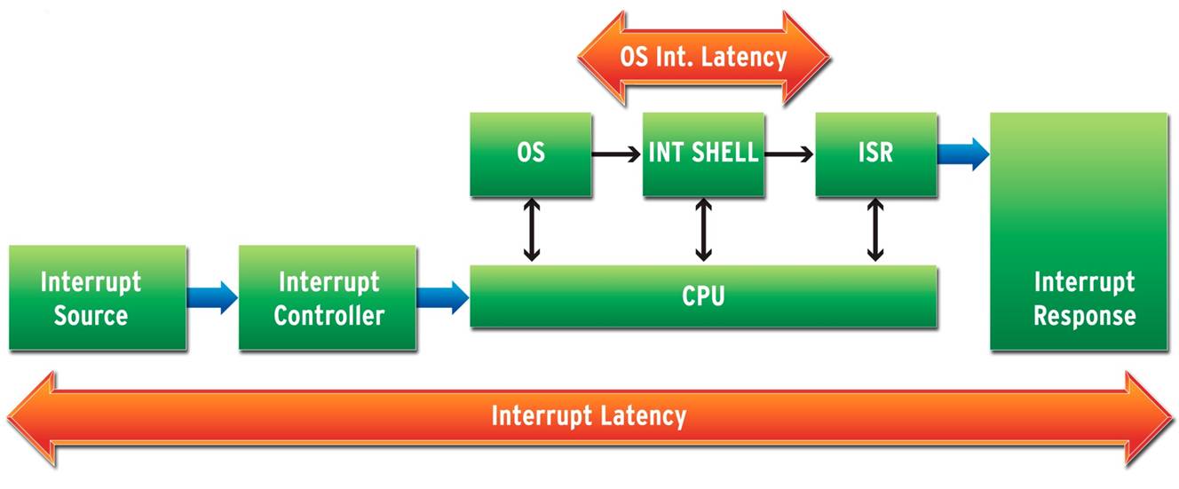 Many vendors use definition #2 because it looks good. Some even quote “zero latency”, which sounds even better. However, this value is not really very useful. #1 has much more practical significance.
Figures quote by RTOS vendors may be useful, once the terminology is figured out, but remember the figure is dependent upon a number of factors which may not align with your system design:
- which platform and interrupt controller is being used?
- clock speed
- cache configuration
- timer frequency
- what kind of memory is the RTOS running out?
- was the kernel built optimized for speed?
Clearly it might be more useful to make the measurement yourself.
To measure short time intervals in any electronic system, you need an instrument. And the best tool for this kind of job is an oscilloscope. One approach is to use one pin on a GPIO interface to generate the interrupt. This pin can be monitored on the ‘scope. At the start of the interrupt service routine, another pin, which is also being monitored, is toggled. The interval between the two signals may be easily read from the instrument.
I can imagine that a software engineer may be appalled by the thought of using an oscilloscope, but this might be an ideal opportunity to liaise with your hardware design counterpart. Actually, such liaison might be a good idea anyway …
If this topic particularly interests you, a free white paper may be downloaded from here.
Comments
Leave a Reply
You must be logged in to post a comment.
Dear sir,
How we can minimize the Interrupt latency…?
Some of Author includes Interrupt response time into Interrupt latency,so according to them by writing small ISR ,one can minimize Interrupt latency..Is that so..?
@pranav: Of course, a short/fast ISR helps, but you must consider the other factors I mentioned. Otherwise, it is all down to what RTOS you are using.