Development of the ECAD/MCAD collaboration (IDX) standard

ECAD/MCAD collaboration is essential as the complexity of electronic designs has become substantially more evolved and spans across multiple design disciplines. In current working environments, product designers are no longer bound to a single geographic location. Many products are developed through collaboration with teams that work across multiple countries and continents, which presents challenges when communicating between the different designers and engineers in an electro-mechanical system.


One of the pivotal standards to facilitate communication between electrical and mechanical domains is the IDX standard. The main goal of the IDX standard is to allow electrical and mechanical designers to communicate and propose new changes at any time or frequency. This allows designers to provide the design intent on the changes that need to be made and ensure that the two domains stay synchronized throughout the design cycle. This allows designers to detect issues early on, rather than spending a significant amount of time re-working a design due to interferences and mismatch in data at the very end of the design.
To ensure that only the required information is shared, the IDX protocol provides several mechanisms to control the data being sent from either domain to ensure only the newly added, deleted or modified data is sent. Below is a description of the IDX types that can be sent between ECAD and MCAD:
- Baseline – Contains the complete design at the current stage of the design process. This creates the unique identifiers for each element in the design to allow incremental data exchange.
- Proposal – Contains only the incremental data indicating objects that have been added, modified or deleted from the design.
- Response – Replies to the current proposal file. Defines the elements that have been accepted or rejected.
- External – Contains non-collaborative elements for a one-way transfer from ECAD to MCAD including copper, soldermask and other ECAD data objects.
To ensure alignment between the PCB design in ECAD and mechanical assembly in MCAD, both domains must understand the design objects used on either side. Exposed copper plays a significant role in the development of the mechanical assembly. Assembly models that are seated on the surface of the substrate could cause irreparable damage to the characteristics of the PCB design. IDX provides a higher resolution of data that can be transferred between both domains to ensure that these interferences do not occur and potentially avoiding costly re-spins of the PCB design or redesign of the mechanical assembly.
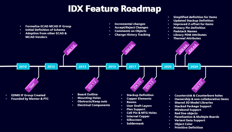
In 2010, the ProSTEP iVIP ECAD/MCAD Collaboration IF was formed and is still going strong today. Throughout the last decade the schema has been updated to support new objects and mechanisms to collaborate advanced data between the electrical and mechanical domains. This includes, stackup information, flex support, copper data, attribute information and many more design elements. This allows not only designers to be capable of collaborating on designs being developed today, but also for the future.
Austin, Texas was the setting for this year’s annual face to face meeting of the ECAD/MCAD Collaboration (IDX) standard steering committee. Over three days, representatives gathered from across the globe including Cadence (USA/Canada), Siemens (USA), Zuken (Japan), Dassault (France), PTC (UK/Israel), Maya HTT (Canada) and Desktop-EDA (Australia).
Strong progress was made on a range of key actions that will strengthen the IDX standard. Additional use cases supporting flex and rigid-flex technologies were added. This included the ability to transfer information on the book binder characteristics, data for a non-circular bend of a twisted cable and an anchor point of the primary board in the flex design. Further updates to the cloud implementation were discussed to facilitate new protocols to request and send information between the electrical and mechanical domains. Additionally, there were a range of functionality was quality of life improvements defined to assist the collaboration between the designers within the project.
The enhancements to the standard are possible because of the diverse representation of the committee membership that includes most ECAD and MCAD vendors, who are working co-operatively and sharing the needs of their leading-edge users.
The committee will meet online each month, and the next in-person committee meeting will take place in Munich, Germany. Please contact us if you wish to join the ECAD/MCAD collaboration discussion!
Project Chair: Alex Grange: alex.grange@siemens.com
Project Coordinator: Brian Watson: brian@desktop-eda.com.au