AA battery replacement project tutorial #2: USB-C

This entire project is intended to be done within the free trial period.
[This is Part 2 of the tutorial, for Part 1 click HERE]
Open Schematic
Double click your saved schematic to open and continue where we left off from

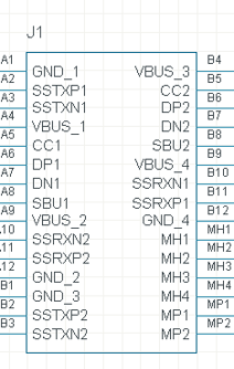
USB411503C
If you followed the previous tutorial, you should now have the USB411503C symbol in your schematic!
Edit Symbol?
In the interest of time, this tutorial does not cover symbol editing.
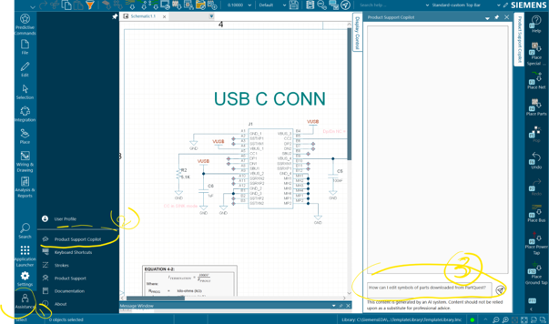
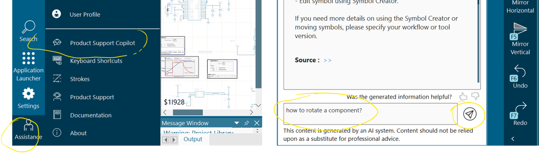
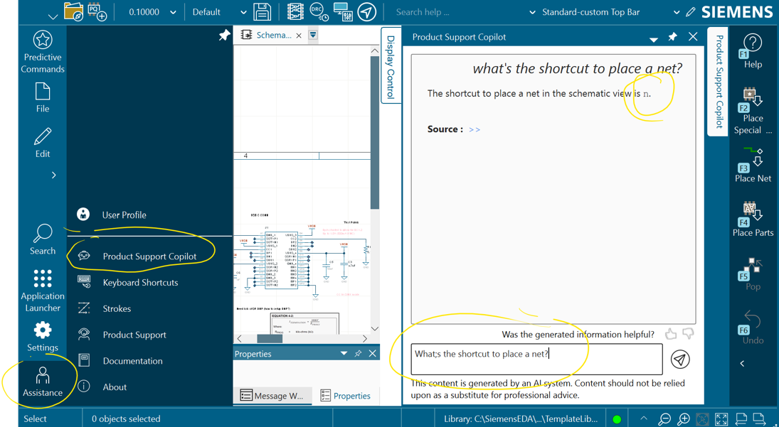
However, if you want to edit your symbol, you can follow steps on the Product Support Co-Pilot as shown in the image below
- Click Assistance on the bottom left
- Click Product Support Copilot
- Pop any question you like as shown in the image below
PartQuest – Reminder!
Here is what we covered in the previous lesson about how to import parts.
Refer to this for the next section!
Reminder Start:
Using the Search Tool again, look for PartQuest and click it
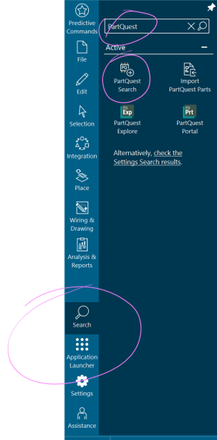
In the search box, look up our battery charger by entering its part number MCP73871-2CCI/ML as in the image below
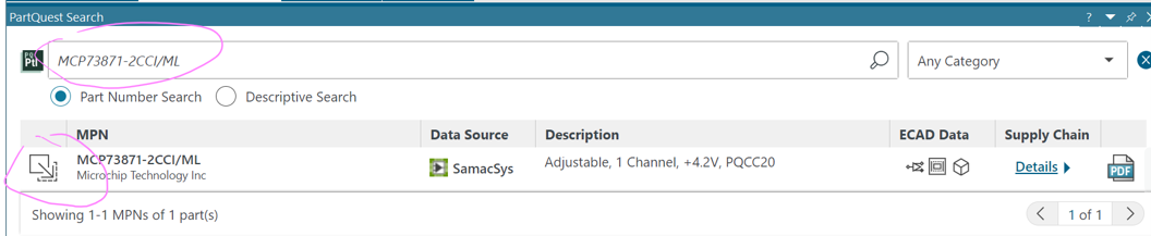
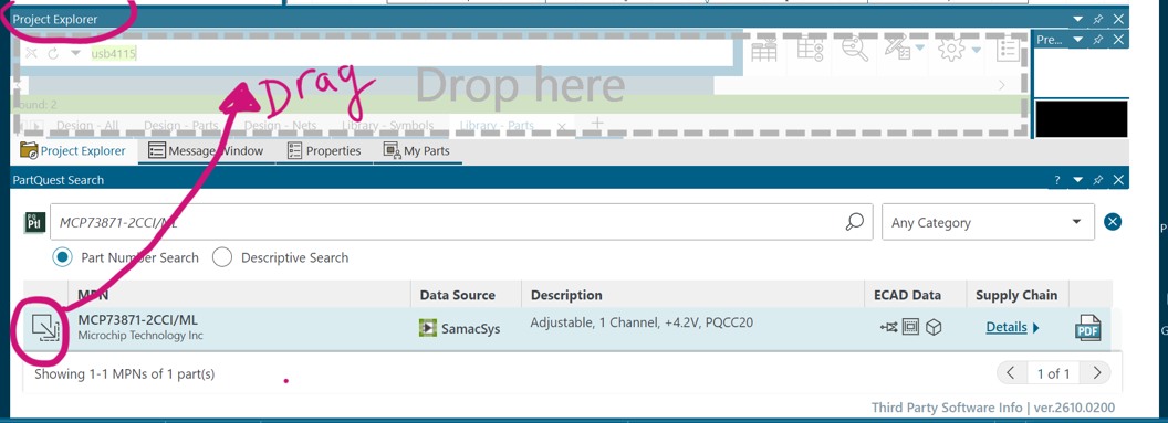
Drag and drop the part into your Project Explorer menu as in the image below
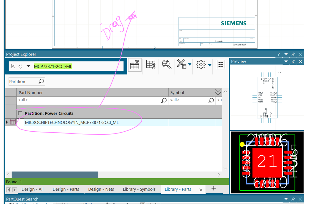
Click and drag into your schematic as in the image below
Reminder End 😏
External Components
Now, let’s use this reminder to find the following components and add them to your schematic:
- RMCF0805FT5K10
- LMK107BJ475KA-T
- KGM21NR71H104KT
- CL21B105KBFNNNE
Arrange Components
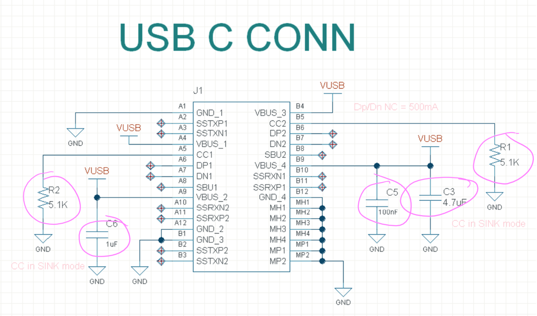
Arrange your components (only those circled in the below image) so that they look something like the image below!
Pro Tip:
Click CNTRL + R to rotate components
ANOTHER Pro Tip:
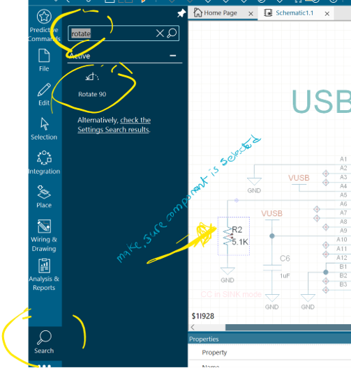
If you wanted to figure out the shortcut for something like “rotate component” yourself, you could either:
- Try searching for “Rotate” in the search tool, or
- Ask the Product Support Copilot!
Pretty cool, right? 😎
Place Power Symbols
There are many ways to place a power symbol.
My favourite is always to find anything I want through the search bar as in the following image.
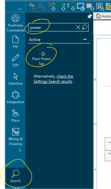
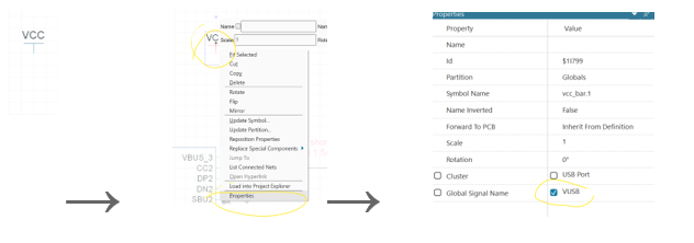
Once you place it, you can right click to select properties, and change its name.
Pro Tip:
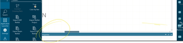
Your menus might be hiding on the edges as in the below image. If that’s the case, you can just use your mouse to drag it out.
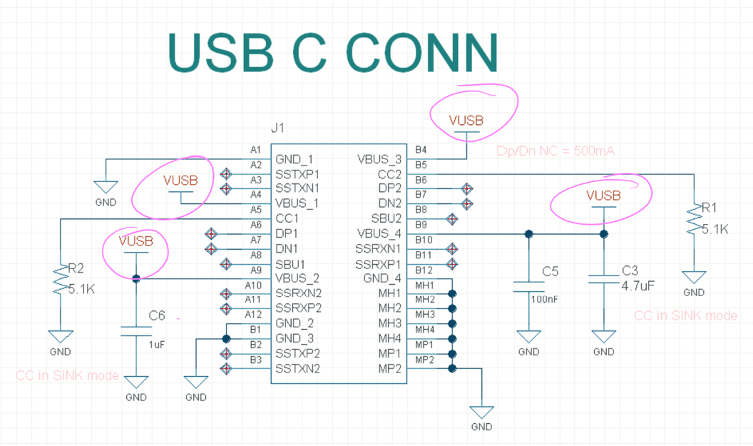
Place VUSB as in the following image (you can CNTRL+C CNTRL+V the symbol as needed):
Place Ground
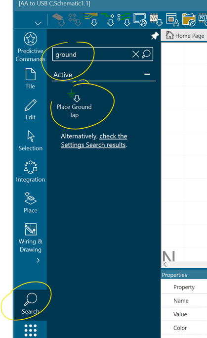
You guessed it, you can just look this one up too!
Now place GND as in the following image:
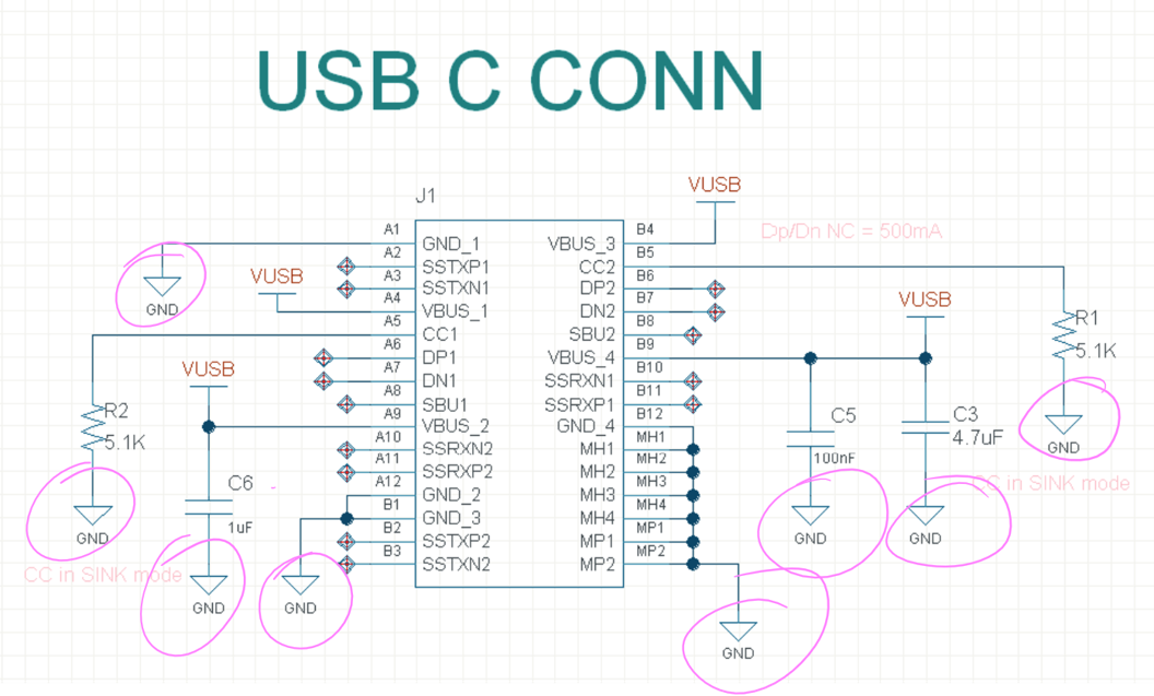
Place Net
Yup, you can just look this one up
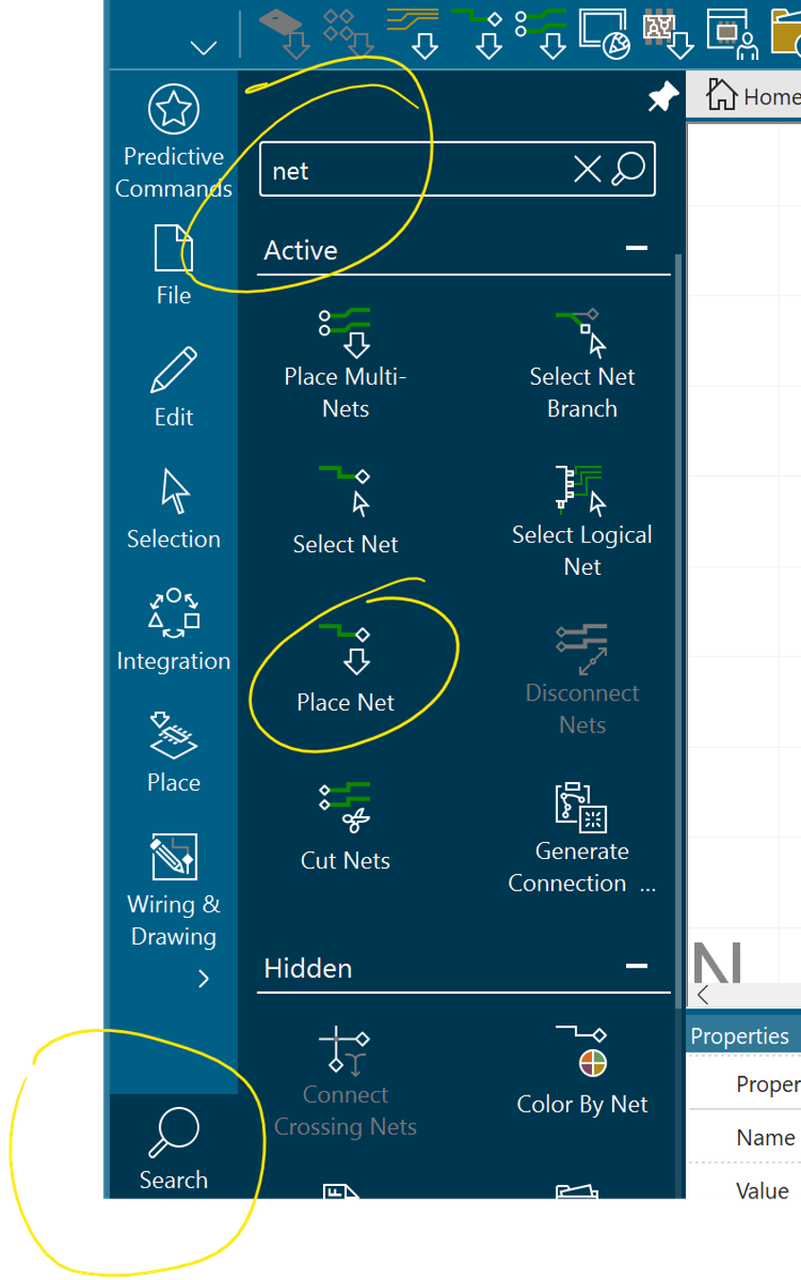
Pro Tip:
Click n (lower case)to place a net
Another Pro Tip: Yes, you could have absolutely asked the Product Support Copilot for the keyboard shortcut yourself!
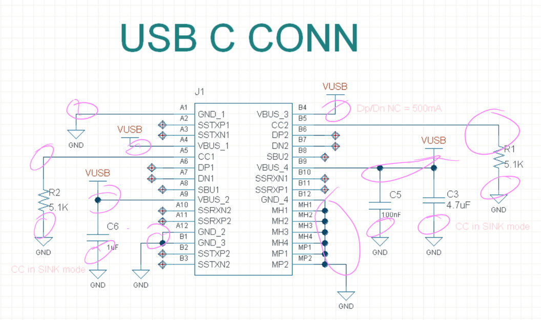
So go do your thing and place nets to connect components as in the following image
Place Text
Can you guess how to place text?
Yup, look it up through the search bar and you can find it in an instant!
Now, can you guess how to edit it?
If you guessed right click → properties, then you’re absolutely correct!
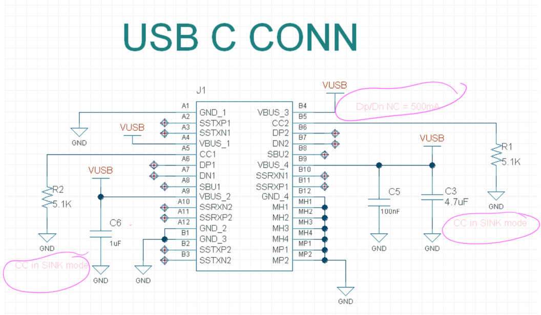
Place text as in the image below, or wherever you see fit.
Place NC
Can you ask the Product Support Copilot for how to place an NC?
See image below!
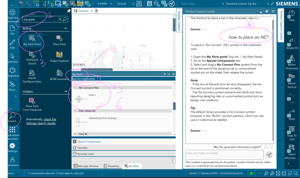
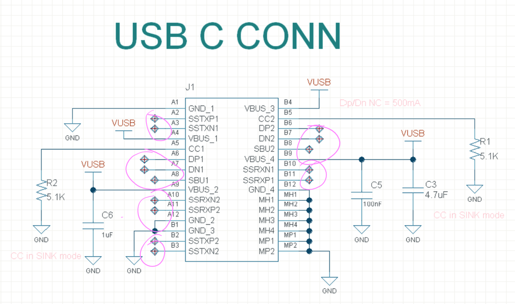
Follow steps given to you by the Product Support Copilot to place NC as in the image below.
Remember to connect their associated nets by clicking n (lower case)to place a net!
Reference Designators
We will do this at the very end, so worry about this for now!
That’s it for today!
Save and close your project, and let’s continue next time. Let me know if you enjoyed this tutorial in the comments!
And if you are struggling with anything, post your issue in the comments and I’ll get back to you as soon as I can.
Have a wonderful Xpedition!