ABCs of PCBs – F for Flexible Circuit Design
Welcome to ABCs of PCBs – a blog series to help new engineers learn about the world of Printed Circuit Boards. I’ll be covering topics from general engineering concepts to PCB design specific rules. As this is a ‘basics’ blog, I’ll keep the content software independent, but any visuals will be from the Mentor PADS Professional PCB suite.
If you missed the last post in this series: ABCs of PCBs – E for Efficiency click here!
When we think of PCB design (which I know we ALL do at some point in our day), we typically imagine designing a stiff green board covered with components. You wouldn’t be wrong imagining PCB design in this way, but did you know flexible PCB design exist too? In a world where so many of our electronics are wearable and mobile, we require flexible circuit technology more and more.

Product creation involving a PCB can happen one of two ways – you either design an enclosure to conform to a board where size and shape are not limited or you design a board and its circuitry to fit the enclosure. Flex PCB technology helps you achieve the latter.
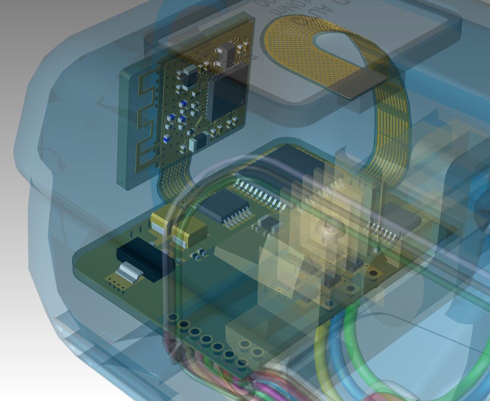
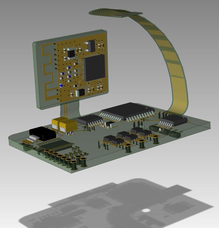
Flexible circuits will usually be seen in flex or rigid-flex PCB designs. Just as the name suggests, flex boards are designed to be flexible – withstanding some bending, vibrations, and folding – while rigid-flex incorporates both rigid board designs and flexible circuits. Each has there own advantages.
Different and thinner materials are required to achieve flexibility, therefore you can create a lighter product. Wearable electronics can’t afford to weigh their users down. Think of wearable clothing for runners with sensors and smaller PCBs. They’re great for gathering real-time speed and posture data, but if they weighed significantly more than regular clothing, runners would probably shy away from these products.
Rigid boards are typically stronger, but shocks and vibrations can kill them. Think of throwing a plank of wood on the ground – the board may stay intact, but you’ve now created microcracks, or even broken the plank all altogether. If that was a rigid PCB, those cracks landing on a trace would prove fatal to your design. Flexible circuits are be designed with vibrations in mind and analysis of designs before manufacturing is key.
Designs with flex segments need to be durable, which enhances product longevity. Most of our mobile daily use and wearable electronics contain flex circuits and need to withstand daily wear and tear. A great example is a laptop. Flexible interconnects are used to pass signals from the keyboard base to the screen and if those were to fail after only one hundred bends, you’d be buying a laptop every few months!
Flexible circuits are the future and we’re inevitably going to see even more new design techniques to accommodate for them in our PCB design tools. We’re already seeing additive manufacturing of PCBs opening up another realm of factors to account for and understand. Learn more about what it takes to implement flex technology in your PCB design with this webinar: Everything You Need to Know About Rigid-Flex PCB Design.
Thanks for reading and see you next time for more on the ABCs of PCBs.
-Shivani Joshi