Are All Post-Layout PCB Design Rule Checkers Created the Same?
The answer is a resounding NO! To prove it, we’re giving away eight electrical DRCs that you can try for yourself. This isn’t just a free trial. The software and rules are yours to keep without obligation.
You’ll quickly find that HyperLynx DRC provides functionality that other PCB design checkers cannot.
Sure, most PCB layout tools have some form of design rule checking (DRC) functionality that is available via a menu pick within the layout tool itself. Some layout-tool DRCs even have access to a rudimentary field solver and ensure that copper-to-copper clearances are met. But, even if copper-to-copper clearances are met, does that imply that the design will work? (Hint: No.)

The point is, it’s easy to compare the “names” of DRCs in PCB layout tools with those in a dedicated design rule checker such as HyperLynx DRC and conclude that they are equivalent. However, the “devil is in the details”… quite literally. To ensure design performance, physical rule checks are not enough; you also need electrical checks.
Take trace segment impedance checking for example. Some layout-tool DRCs only allow you to provide a minimum and maximum allowed impedance value, implying that all trace segments outside the bounds are considered to be violations. This approach may be good enough for quick checks and academia, but it lacks control. As a hardware design engineer, do you really care about every 1-mil trace-segment impedance violation between driver and receiver pins?
Focus on the critical violations
Does a design rule checker make your PCB flow more efficient if you have to comb through 1000’s of design violations to eliminate the ones that you can ignore?
Compared to the cookie-cutter DRC coverage claimed by some PCB design tools, HyperLynx DRC lets you tune DRCs to meet your own needs. For example, you could run the check on a subset of the design or on specific signal nets (called Object Lists). By specifying a minimum trace-segment length violation and maximum combined length of trace segment violations, you can focus your re-route efforts on the most grievous nets.
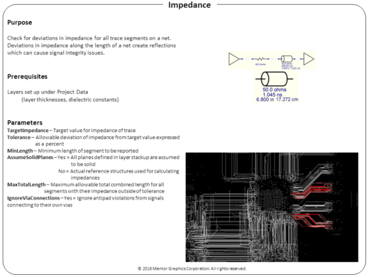
When a trace route includes a signal via, the section of a trace segment that connects to the signal via is routed within an antipad. This connecting trace segment usually has a different impedance because the closest plane layer has been cleared out. Unlike layout-tool DRCs, HyperLynx DRC has settings that let you control whether such trace segments should be included or eliminated from the list of violations. On the other hand, layout-tool DRCs flag all such issues as violations, forcing unnecessary, time-consuming manual investigation.
At Mentor, we’re committed to improving the PCB design flow of hardware design engineers, so we’re giving away HyperLynx DRC with eight DRC rules. No charge. No maintenance. Just free.
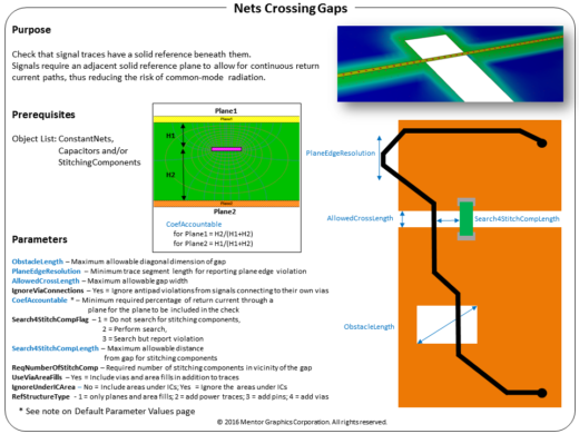
The free version even includes the “nets crossing gaps” DRC, which helps identify sources of EMI and nets crossing gaps in copper shapes.
HyperLynx DRC works the way you do
HyperLynx DRCs can be customized as per your corporate or technology guidelines. And, through the ODB++ and IPC-2581 formats, designs from any layout tool, including Altium® Designer, Cadence Allegro®, Mentor’s PADS® Layout and Xpedition® PCB, and so on, can be imported into HyperLynx DRC. Need more rules? Fourteen additional rules can be purchased on a subscription basis and larger rule bundles are also available as your needs change.
Free software + the opportunity to improve your PCB design flow = a no brainer. Get started today.