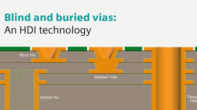
Should I Simulate Split Planes ?
Almost all modern ICs require multiple supply voltages to operate, making power integrity one of the biggest problems in electronic product design. Many times, analog ground and digital ground are kept separate on the board to avoid induction of noise from one part of circuitry to another.
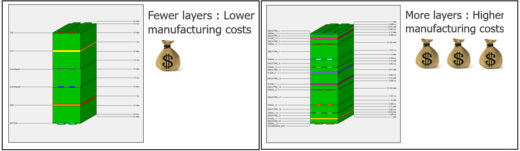
It is impossible to assign a separate layer for each of the power planes. Even if the designer could somehow have an individual layer for each power net, it would unnecessarily increase the number of vias used or make the board unnecessarily complicated and susceptible to noise and board failure. Also, having more layers in the stack up increases the manufacturing cost of the board.
In such scenarios, the use of split planes can create compact and more-reliable board designs. Using split planes reduces the number of plane layers and makes the design more compact and efficient.
Unfortunately, having split planes in your design means having non-ideal planes so it’s important to perform DC drop analysis to make sure there is enough copper on your planes. It’s also important to make sure that there are no “hotspots” on your planes. If there is a large amount of current flowing through a small amount of copper, it can create excessive heat on your board.
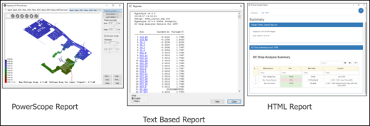
PADS® HyperLynx® DC Drop offers detailed reports in text, HTML, and visual format.
For a detailed description of how to create split planes and perform DC Drop analysis take a look at my webinar, “Managing Split Planes and Power Integrity.”
PADS HyperLynx DC Drop allows you to quickly identify problems with voltage drop and current density for all the voltage rails on your PCB. Reduce time to market by finding power-supply problems before your boards are released.