Designcenter | Tips and Tricks | Assemblies and Magnetic Snap

In this Tips & Tricks session we will have a look at assembling components more efficiently by utilizing the “Magnetic Snap” functionality. “Magnetic Snap” is a great usability improvement that will make your workflow more efficient and streamlined while creating assemblies.
What is the Magnetic Snap functionality?
The “Magnetic Snap” functionality is part of the Auto Align assembly constraining option. As the name implies, the functionality works while in the Auto Align dialogue, dragging a component to its intended position using the mouse and cursor location in combination with preselection of entities in the graphical window. The Alt key can be used if you only want to move the component without snapping to any other entity and create an unwanted assembly constraint. It can also be used to create persistent assembly constraints or transient constraints while only moving a component using assembly. A great addition is that you can press and hold the Control button while dragging a selected component and quickly create a copy of that component. You do not necessarily need to use faces specifically, but Magnetic Snap will also work with CSYS, datums, routing objects and elliptical edges. Another functionality added is the creation of smart simultaneous Touch and Align constraints.
Magnetic Snap under the Auto Align Assembly Constraint Function
Let’s take a look at our specific example and show the great Magnetic Snap functionality.
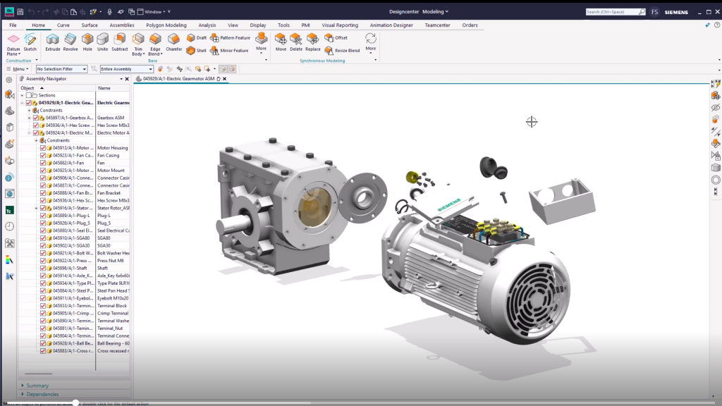
We will be looking at a limited area of an Electric Gearmotor, and more precisely the actual Junction Box assembly. Let’s make the Electric Gearmotor the Displayed part, as it is at this assembly level where we want to add the required constraints. Here, a colleague has added the parts needed, but scattered, and so our task is to create the appropriate assembly constraints and position the Electric Junction Box and its components properly. To compare and really show the benefits we start adding constraint by constraint using the traditional way and manually match face pairs. First, we manually create a touch constraint for the bottom of the casing, and then we continue by aligning the mounting holes to the intended corresponding faces. In the Assembly Navigator we note that the three manual defined constraints are created.
Comparison of using the functionality
To demonstrate the Magnetic Snap Functionality and compare we Undo, to get rid of all the Assembly Constraints just created. We again select the Auto Align Function and turn on the “Prefer Center/Axis Over Object” option, that enables to snap to the axis of objects regardless of face selected.
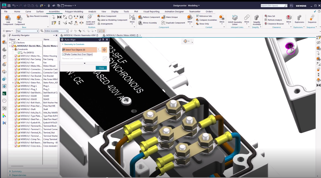
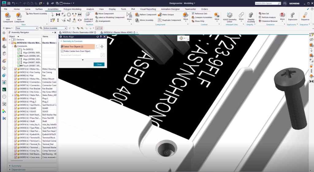
You can then simply move your cursor over the component and object to be positioned, press and hold the left mouse button while dragging the component to your intended position. In this case we will drag it to the mounting screw hole face of the motor casing. The target face lights up, and the component snaps to its new position. Releasing the mouse button creates the desired constraints. Note here that the system smartly finds two constraints and adds them. Let’s continue by aligning the hole on the other side as well to fully constrain the Junction Box Casing. In the same way we constrain the Top Cover by simply dragging the mounting hole face to the matching screw hole face. Again, see here that two constraints are created. To fully constrain we align the hole on the other side as well.
Creating different results
While positioning the screw to the mounting hole we will dig a bit deeper to the functionality of the Magnetic Snap. Depending on where you select on the cylindrical face, at the ends or in the center, you will have different results. Let’s have a look at how that works. If we grab the screw at the bottom end of the cylindrical face and drag it to the desired position the system will create two constraints locking it to the entrance of the hole’s destination.
If we now Undo and grab the screw at the center of the cylindrical face and drag it to its desired position, this will create a single Touch Constraint, and the screw can still rotate and move in the actual direction of the hole.
Now if we Undo again and grab the screw at the top end, near the head, and drag it to its desired position in the mounting hole, two constraints are automatically created with the smart finding of the system. As there is no screw component for the other hole we simply press and hold the Control key while dragging the component to, first a new rough position, and finally to its final constrained position. You can also do this in one go if required.
Finalizing your assembly
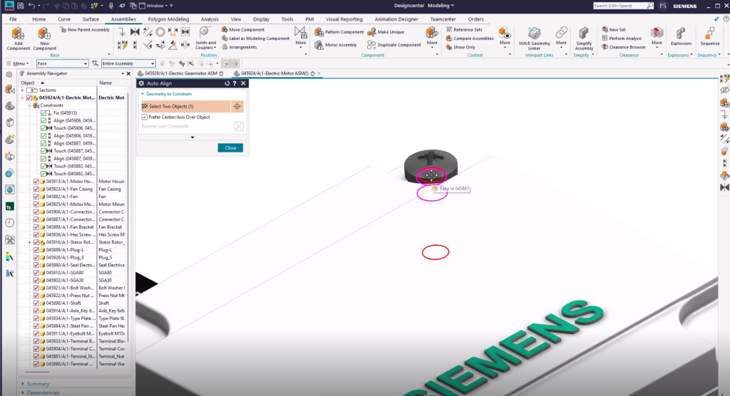
As there is no cabling here, we need to plug the incoming and outgoing holes for the electrical cable. Looking closer to the cap, the shape indicates that we need to be careful what entities we select for dragging. We select the cylindrical face at the bottom and drag it into its intended position. Assessing the constraints shows that it’s not positioned the way we require, hence we Undo and Redo the drag operation with the more strategic cylindric shape of the head of the CAP while dragging. Assessing the Assembly constraints shows that it is now constrained correctly. We repeat for the final Cap and now the assembling work is done for Electric Junction Box.
Continuing your journey with Designcenter