Computer Aided Engineering in the Industrial Metaverse – Part 2
The Industrial Metaverse (IM) is a virtual world in which one can interact with the digital twin. From a Computer Aided Engineering (CAE) perspective, that requires the digital twin to not only be photo-realistic, but realistic to the extent where its behavior conforms to the physics of the real world.
Beyond Pretty Pictures
Real-time and interactive physically-realistic and photo-realistic representations of the digital twin are the heart of the IM. Despite this, during product design, engineering design decisions are made based on quantified KPIs. Although simulation based IM 3D scenes are compelling for a wide range of audiences and user personas, critical KPIs need to be incorporated to enable engineering judgments to be made.
NVIDIA’s Omniverse provides capabilities that, coupled with Siemens’ Xcelerator platform, are helping to define the IM. Omniverse is customizable to the extent where bespoke heads-up-displays (HUDs) can be included in an IM scene. These HUDs can then be utilised to both tailor the scene interaction as well as presenting relevant engineering KPIs.
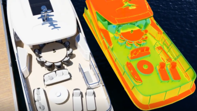
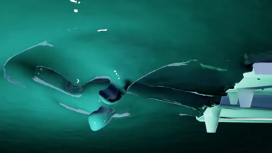
The following animation, rendered from an interactive IM session, includes pre-solved Simcenter STAR-CCM+ hydrodynamic (6 degree of freedom, free surface) and external aerodynamic simulations of a yacht (courtesy of Princess Yachts) . The HUD, in addition to allowing camera selection, or camera@time-moment interaction, presents performance and environmental KPIs that are synced with the simulated transient behaviour. These include the pitch and heave of the yacht when under acceleration and cruising, as well as environmental parameters such as fuel consumption and CO2 emission. The first part of the animation presents a predefined animation, the second part an interactive approach.
Interactive Physics Simulation
The term ‘real-time simulation’ can be considered a misnomer. The last thing you’d want to interact with in ‘real-time’ is a flight profile that might take 8 hours! Conversely, viewing a simulated microsecond phenomena would be over, literally, in a flash.
‘Interactive simulation’ is a better term in that it accommodates both the ability to make changes in the IM and to then see the physical ramifications of those changes reflected back instantaneously in the IM scene.
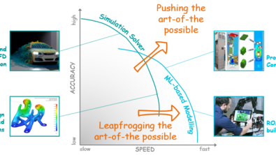
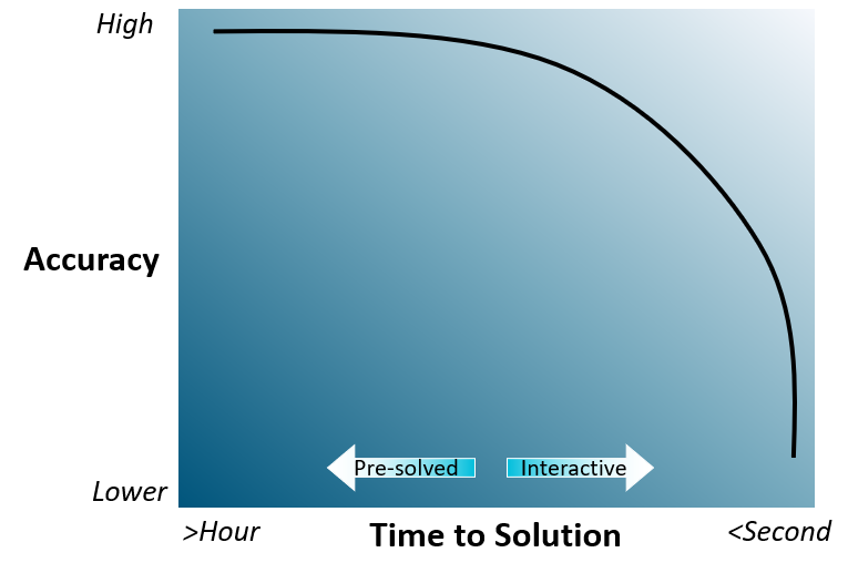
Interactive physics simulators come at a price though. A full fidelity ‘engineering grade’ 3D simulation can take at least minutes, if not hours (sometimes days) to generate. The simplest algebraic equation physics models can be solved instantaneously. Between these 2 extremes is a trade-off between accuracy and simulation time.
The Simplest Algebraic Models
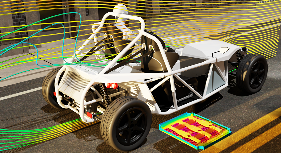
Low order interactive physics simulators, those capable of providing but a small number of parametric outputs, still offer opportunities for interaction and integration into the IM. The following example shows how a simple Rja=f(Power, Ambient Temperature) algebraic relationship can be used to predict electronic component temperatures and to have those temperatures used to both colour and scale (on over-temperature conditions) the corresponding IM objects. In this case 4 out of the 96 power MOSFETs on the Simrod DC-AC inverter board.
Functional Mock-up Units
The FMI standard documents an approach by which any type of parametric model is authored as an executable dll, wrapped in an XML container, with well defined input/output interfaces. Any instance of this is called an FMU (Functional Mock-up Unit). An obvious candidate format for an Executable Digital Twin (xDT) that really comes into its own when considering the IM in the context of mirroring an already existing product or process.
The following animation presents an IM session where a back-end FMU is interfaced, via the HUD, so that an interactive experience is enabled whereby the throttle location of a yacht, input via the HUD, drives the yacht velocity and thus translation. The FMU is authored from a propulsion model in Simcenter Amesim. Admittedly this very simplistic parametric model (1 input, 1 output) doesn’t make for the most entertaining of ‘drive-sim’ experiences, but does at least demonstrate the approach by which an FMI interface can be used to integrate a digital twin xDT with an Omniverse enabled IM scene.
The Best of All Worlds
The trade-off between simulation time and simulation accuracy has and continues to be actively addressed by CAE software vendor roadmaps. Modern NVIDIA GPU compute infrastructures and corresponding adaptions of the numerical methods developed to capitalize on these opportunities are evolving hand-in-hand.
Although there are interactive 3D physics simulators available today that purport to be able to predict complex 3D physics phenomena, these are commonly only required to pass a visual inspection test. A ‘does it look realistic’ verification test that’s all that’s required to engage movie audiences.
Engineering requirements however demand a much more rigorous and accurate verification. But still, there is the continued desire to provide engineering grade high fidelity results in an interactive IM context.
Model Order Reduction offers hope, whether via Krylov subspace projection methods or Proper Orthogonal Decomposition, or even Machine Learning coupled with PiNN approaches. Suffice to say the industry is not there yet. To have engineering grade accurate solutions in ‘real-time’ (or rather ‘interactively’) is a goal, not yet fully realised, but one that should and will be achieved.
Did you read Part 1 of this blog? Catch up here: Computer Aided Engineering in the Industrial Metaverse – Part 1
Disclaimer
This is a research exploration by the Simcenter Technology Innovation team. Our mission: to explore new technologies, to seek out new applications for simulation, and boldly demonstrate the art of the possible where no one has gone before. Therefore, this blog represents only potential product innovations and does not constitute a commitment for delivery. Questions? Contact us at Simcenter_ti.sisw@siemens.com.
