Behind the Design: BAE Systems
This is the ninth post in a series showcasing the winners of the 2014 Technology Leadership Awards. View the previous ones here.
Runner up in the Military & Aerospace category: BAE Systems, United Kingdom.
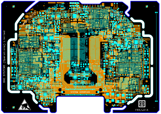
Design: Binocular helmet mounted display
The system is a major advance in helmet-mounted heads-up display technology and includes a binocular display, opto-inertia head tracking technology, fast response times, and fully-integrated digital night vision camera.It also meets all weight and size targets and provides improved comfort.
Design team:
- Matthew Offredi, Gary Chambers, Daniel Smith, Sammy Laver, Ross McCullie, Gary Prior
Design challenges:
- The helmet was designed concurrently by the electronics, mechanical, optical and system design teams. This concurrent design approach aided in solving issues across the complete system, but this organic environment meant that there were a number of iterations during the design process.
- Weight / CoG (center of gravity): Helmet designs are subjected to ejections tests and therefore weight/mass and CoG is a critical driver in the design.
- Power and thermal have to be managed carefully to reduce thermal effects (to avoid cooking a pilots head).
- Keep-out areas were needed in areas that were subject to head impact, which constrained component skyline and placement.
- An irregular board outline was needed as the module mounted to a helmet.
- Design testability, both in production and maintenance, is a key driver in the design.
- The major challenge with these devices was the breakout and subsequent routing because the pins were 94% utilized.
- The design team only had a small window of opportunity to take the design from a concept stage into a fully working product. This short project duration was driven by compressed project time scales, but achieved by using great engineering techniques, a motivated and empowered team, and a number of learn first activities.
Design tools and team comments:
- Board Station, Hyperlynx®, and ICX
- All SI was completed with ICX so the board worked first time.
- There are ~400 signals classified as high speed on the design. The signal integrity strategy required that these signals were grouped and simulated as “what if” Hyperlynx and ICX simulations which drove the schematic topology. This included ensuring that suitable return vias were placed close to any signal layer transition points, to guarantee a good signal return path. The post-routed board was fully simulated in ICX and this was repeated, iteratively, as the design progressed, until the optimum solution was found.
- The breakout vias perforated the plane areas beneath the FPGAs, so the team used the Hyperlynx Power Integrity tool to analyze and determine if sufficient current was being delivered, and if the current density was not excessive in any area. The high power rail count (31) required careful management.
Judge’s comments
- “Very nice power distribution work. Very dense placement.”
- “This board overcame many restraints that are not normally found in most boards. Different thermal restrictions and keep out areas on each side of the board, height restrictions, and an odd shaped board, to name a few. In addition, the electrical, testing, and human engineering make this board a challenge. They provided and excellent description of what they had to overcome.
About the Technology Leadership Awards
Started in 1988, this program is the longest running competition of its kind in the electronic design automation (EDA) industry. It recognizes engineers and designers who use innovative methods and design tools to address today’s complex PCB systems design challenges and produce industry-leading products. See the full list of 2014 winners here.


