Remove common reverse engineering obstacles with Convergent Modeling
Being able to speed up engineering tasks is great, but what if companies could eliminate some of those tasks for good? Answering this question was important to Siemens PLM when it began developing Convergent Modeling. The surfacing step of reverse engineering, the step which can cause serious bottlenecks that delay downstream work, is eliminated.
In part one on his series about Convergent Modeling, George Allen describes the vision that drove this new reverse engineering modeling approach, how this new approach compares to the old approach and how companies have the ability to use partly curvy and partly facetted, or “mixed,” objects.
Here, he discusses the technology behind the new system’s architecture and how it partners with the abilities of modern CAD systems.
The technology
With the Convergent Modeling technology workflow entirely eliminating the surfacing step, the resulting object is rather strange by traditional standards.
 With the surfacing step gone in this new reverse engineering process, you get an object you don’t traditionally see.
It is a mixed object that is partly facetted and partly curvy. The green and pink faces are facet “meshes” (collections of triangles), but the blue and red faces are analytic cones and cylinders (curvy surfaces), respectively. The two previously separate modeling approaches have converged.
The red holes will probably be made by drilling, and the cylindrical surfaces provide accurate size and center-point information to support this. The green region is very finely facetted, so its shape is good enough to support CNC milling operations to create tooling. So, the mixed object provides the information we need for these manufacturing operations.
Our approach has been to make these mixed objects work in all operations throughout the Siemens NX software package, including modeling operations, visualization, mass properties analysis, finite element analysis, packaging/clearance/clearance checking, NC operations and so on. By doing this, we remove the need for laborious surfacing tasks.
Using CAD history-based operations
In the above example, we saw a case where the surfacing step was eliminated entirely. In other cases, surfacing can be removed from the critical path, even if it is not eliminated. The key here is the ability of modern CAD systems to “replay” the history of a design with new inputs.
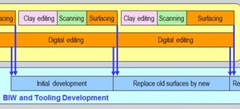
The diagram below shows a typical workflow in the automotive industry. First, the styling department creates the outer “Class A” surfaces of the vehicle. Quite often, stylists create clay models, scan them and then fit surfaces to the 3D scan data.
Next, the class A surfaces are released to downstream engineering groups who develop structural body parts (“body in white”, or BIW) and tooling. Obviously, the downstream BIW and tooling work cannot begin until the outer “class A” surfaces are available, so, as we have seen before, the surfacing step is a bottleneck.
 This is the traditional reverse engineering process.
But, with Convergent Modeling technology, the downstream activities can begin early on, using facetted versions of the class A surfaces. Later, when the final surfaces become available, they can be used to replace the facetted versions.
 This is the new reverse engineering process: Convergent Modeling.
A modern history-based CAD system remembers the “recipe” of each object — in other words, it records the sequence of operations that was used to create the object. The recipe can be replayed with new inputs, which provides an extremely powerful form of editing.
Using this technology, the BIW and tooling models can then be “replayed” each time new versions of the class A data become available. The work schedule is compressed, and there is a reduction in the workload of highly-skilled surfacing experts, freeing up their time for more creative work elsewhere.
Summary
A new Convergent Modeling approach allows facetted models to be used directly in CAD functions instead of undergoing “surfacing” conversion first. Eliminating or reducing the surfacing work obviously cuts labor costs. It also cuts schedules because downstream activities can start sooner.
The bottom line — the fastest and most efficient reverse engineering process is the one that you don’t have to perform!
This concludes our introduction to Convergent Modeling.
About the author
George Allen has more than 35 years of experience in developing CAD software and in helping major corporations use it to improve their productivity. He is recognized worldwide as a leading expert in the field both by academics and industry executives. George has led the development of several new technologies in the NX CAD software, especially in the area of geometric design. His advice and guidance have served to improve productivity at some of the world’s largest manufacturing companies, including GM, Nissan, Honda, Boeing and Canon. George received his Bachelor of Science degree in mathematics from the University of Sheffield and his Master of Arts degree in mathematics from the University of California.